
Method for detecting surface dirt defect of image sensor

An image sensor and image detection technology, which is applied in the direction of instruments, measuring devices, scientific instruments, etc., can solve problems such as prone to missed detection

Active Publication Date: 2016-12-14
深圳睿晟自动化技术有限公司
View PDF6 Cites 8 Cited by
  • Summary
  • Abstract
  • Description
  • Claims
  • Application Information

AI Technical Summary

Problems solved by technology

[0003] The purpose of the present invention is to provide a method for detecting dirt defects on the surface of an image sensor, aiming to solve the problem that in the prior art, the detection of dirt defects on the surface of an image sensor using a uniformly luminescent light source is prone to missed inspections

Method used


Image

  • Method for detecting surface dirt defect of image sensor
  • Method for detecting surface dirt defect of image sensor
  • Method for detecting surface dirt defect of image sensor

Examples


Embodiment Construction

[0015] In order to make the object, technical solution and advantages of the present invention clearer, the present invention will be further described in detail below in conjunction with the accompanying drawings and embodiments. It should be understood that the specific embodiments described here are only used to explain the present invention, not to limit the present invention.

[0016] It should be noted that when an element is referred to as being “fixed” or “disposed on” another element, it may be directly on the other element or be indirectly on the other element. When an element is referred to as being "connected to" another element, it can be directly connected to the other element or indirectly connected to the other element.

[0017] It should also be noted that the orientation terms such as left, right, up, and down in this embodiment are only relative concepts or refer to the normal use state of the product, and should not be regarded as limiting.

[0018] Such a...


PUM


Abstract

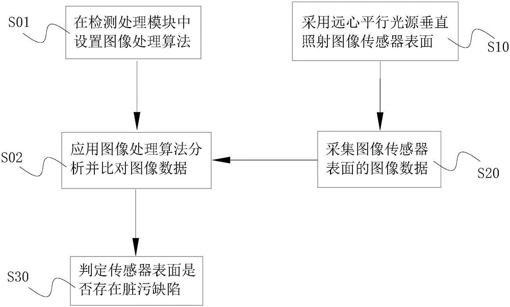
The invention provides a method for detecting a surface dirt defect of an image sensor. The method comprises the following steps: step S10, irradiating the surface of the image sensor through a telecentric collimated light source; step S20, starting an image sensor, performing imaging to the surface of the image sensor, and collecting the surface of the image sensor and forming image data of surface dirt defect particles; and step S30, obtaining a detection result about whether a surface dirt defect exists on the surface of the image sensor according to the image data. According to the method, the problem of missed detection that is prone to happen when an image sensor is subjected to surface dirt defect detection through a uniform luminescence light source in the prior art is solved.

Description

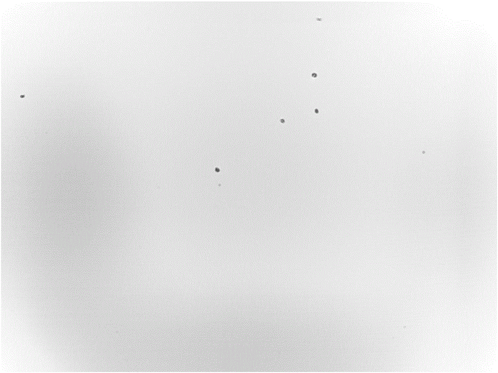
technical field [0001] The invention relates to the technical field of electronic component detection, in particular to a method for detecting dirt defects on the surface of an image sensor. Background technique [0002] In the prior art, when detecting surface contamination defects on an image sensor, a uniformly luminescent light source is placed about 5 cm above the image sensor to be tested, and the light emitted by the light source shines on the surface of the image sensor to make the surface dirty. Defect imaging for detection. The disadvantage of this method is: since the surface bearing the dirty defect may be the photosensitive surface of the image sensor or the surface of the filter above the image sensor, and the light emitted by the uniformly illuminated light source is diffusely reflected by the backlight to form Dirty particles on the surface cause boundary effects, making the edges of the obtained particle image extremely blurred, and it is easy to miss detec...

Claims


Application Information

Patent Timeline
IPC IPC(8): G01N21/47
CPCG01N21/4738G01N2201/061
Inventor 谢煜何岗宋洋温柳康
Owner 深圳睿晟自动化技术有限公司
Learn More