Cell assembly device

A cell assembly and cell technology, which is applied in battery assembly machines, secondary battery manufacturing, sustainable manufacturing/processing, etc., can solve problems such as interruption of upper cover loading operation, impact on battery production efficiency, and interruption of battery production process

Inactive Publication Date: 2016-12-14
DONGGUAN ALI AUTOMATION CO LTD
View PDF7 Cites 25 Cited by
  • Summary
  • Abstract
  • Description
  • Claims
  • Application Information

AI Technical Summary

Problems solved by technology

[0007] When the trolley is stacking the upper cover, the manipulator stops and waits, causing the upper cover loading operation to be int

Method used


Image

  • Cell assembly device
  • Cell assembly device
  • Cell assembly device

Examples


Embodiment Construction

[0099] The invention discloses a battery cell assembling device, so as to realize the continuous feeding of the upper cover and improve the production efficiency of the battery.

[0100] The technical solutions in the embodiments of the present invention will be clearly and completely described below with reference to the accompanying drawings in the embodiments of the present invention. Obviously, the described embodiments are only a part of the embodiments of the present invention, but not all of the embodiments. Based on the embodiments of the present invention, all other embodiments obtained by those of ordinary skill in the art without creative efforts shall fall within the protection scope of the present invention.

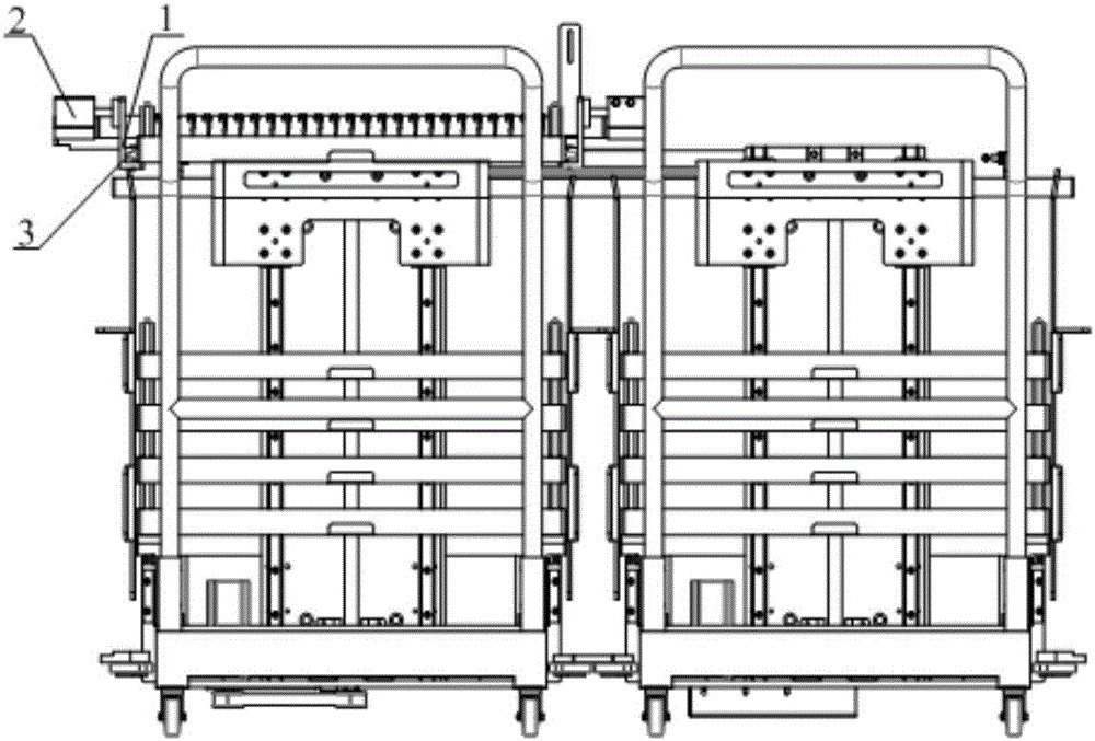
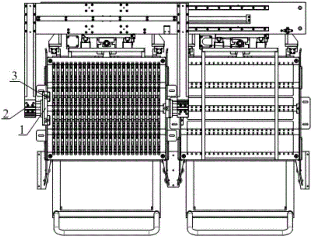
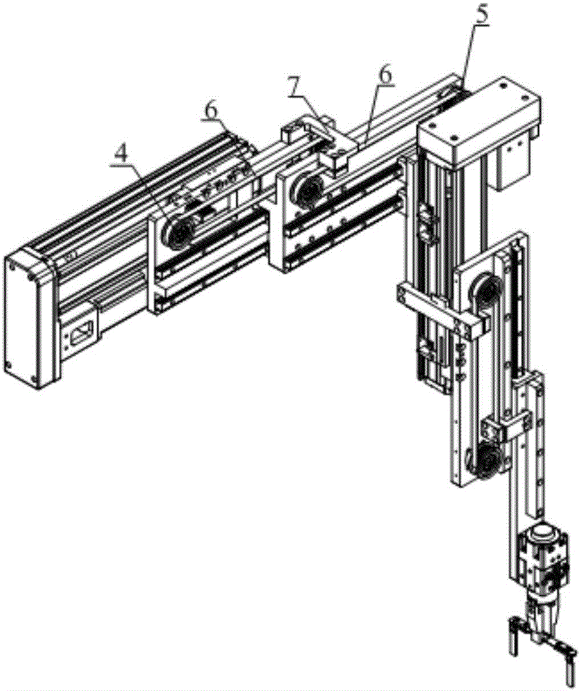
[0101] see Figure 1-Figure 12 , figure 1 A schematic structural diagram of the feeding frame provided by the embodiment of the present invention; figure 2 The top view of the feeding frame provided by the embodiment of the present invention; image 3 A ...


PUM


Abstract

The present invention discloses a cell assembly device. The cell assembly device comprises a feeding frame, a mechanical arm assembly for grabbing an upper cover, a flexible connection shaping device for shaping a flexible connection, a cell feeding device, a cell positioning device, an ultrasonic wave welding device, a cell dedusting device, a plastic coating device, a plastic clamping device, a film recycling device, a plastic folding device and a cell entering-shell device. Due to the feeding frame, upper covers are fed constantly, and the mechanical arm assembly does not stop and wait, so that the production efficiency of the cells is improved. Due to the positioning device, a material tray is limited in a horizontal direction, the positioning device is matched with a positioning groove on the material tray, and the positioning device and the material tray are in rotating match, so that damage to the material tray is lowered. In the cell assembly device, a film recycling device is added, an unused part of each film is wound with repeated parts of two films, so that operators are prevented from discarding the films randomly, and the working environment of a plant is clear.

Description

technical field [0001] The invention relates to the technical field of lithium battery production, in particular to a battery cell assembling device. Background technique [0002] The battery is a device that converts chemical energy into electrical energy, and the upper cover of the battery is welded to the soft connection. [0003] The process of feeding the upper cover in the prior art is as follows: [0004] The staff sequentially stacks the top covers of the five material trays on the handling trolley until the five material trays on the handling trolley are filled with the top covers, and dozens of top covers are placed on each material tray; [0005] Push the transport trolley filled with the upper cover into the frame for positioning the transport trolley. The manipulator first grabs the upper cover in the uppermost tray to load the upper cover, and after grabbing the upper cover in the uppermost tray, The next layer of the tray automatically rises, the manipulator...

Claims


Application Information

Patent Timeline
IPC IPC(8): H01M10/04
CPCH01M10/0404Y02P70/50
Inventor 李新宏黄光寿
Owner DONGGUAN ALI AUTOMATION CO LTD
Why Eureka
Try Eureka