Road mechanical energy collection apparatus based on mechano-electric effect improvement

A technology of energy collection and effect, applied in the direction of piezoelectric effect/electrostrictive or magnetostrictive motor, generator/motor, electrical components, etc., can solve the problem of low electromechanical effect, achieve high energy conversion efficiency, The effect of easy operation and good overall performance

Active Publication Date: 2016-12-14
CHANGAN UNIV
View PDF5 Cites 12 Cited by
  • Summary
  • Abstract
  • Description
  • Claims
  • Application Information

AI Technical Summary

Problems solved by technology

[0004] In view of the deficiencies in the prior art, the purpose of the present invention is to provide a road mechanical energy harvesting device based on improving the electromechanical effect, which solves the technical problem of low electromechanical effect of the existing energy harvesting device, and is used for road vibration mechanical energy collection and utilization of

Method used


Image

  • Road mechanical energy collection apparatus based on mechano-electric effect improvement
  • Road mechanical energy collection apparatus based on mechano-electric effect improvement
  • Road mechanical energy collection apparatus based on mechano-electric effect improvement

Examples


Embodiment 1

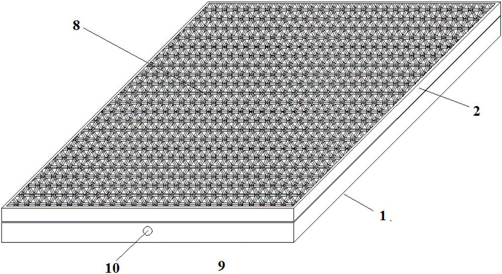
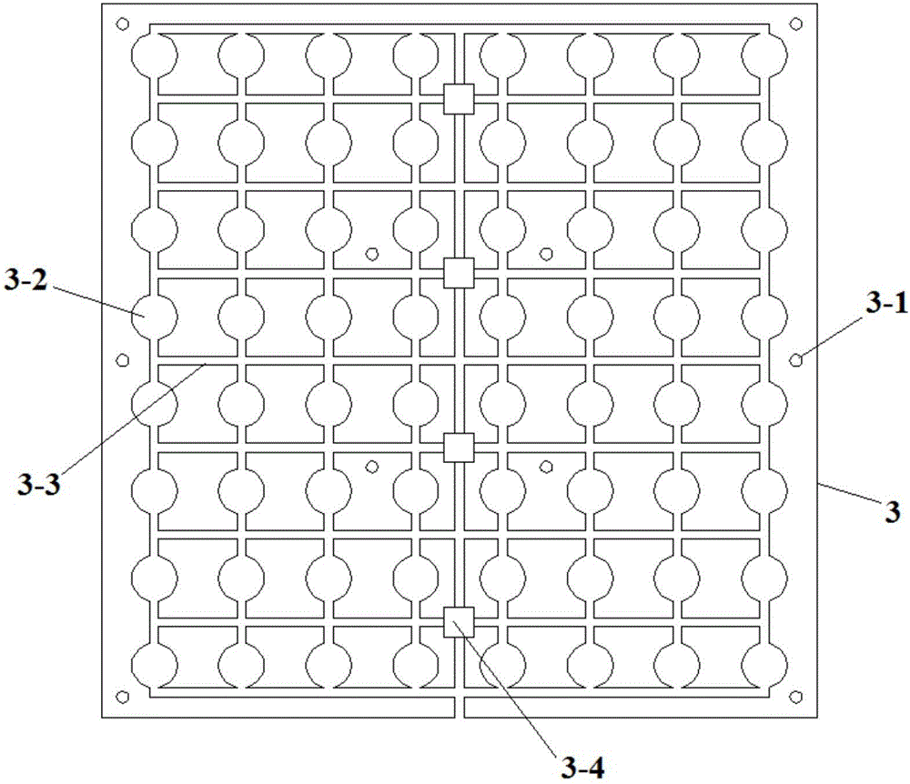
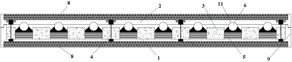
[0041] Comply with the above technical solutions, such as Figure 1 to Figure 6 As shown, the present embodiment provides a road mechanical energy collection device based on improving the electromechanical effect, including a bottom plate 1 and a top plate 2 arranged in parallel with the bottom plate 1, and a piezoelectric power generation substrate 3 is placed on the bottom plate 1, and the piezoelectric power generation substrate 3 is processed with a through hole 3-1, the connecting piece 4 passes through the through hole 3-1, one end of the connecting piece 4 is fixed on the top plate 2, and the other end of the connecting piece 4 is fixed on the bottom plate 1;

[0042] A plurality of evenly distributed installation blind holes 3-2 are processed on the piezoelectric power generation substrate 3, and the installation blind holes 3-2 are connected through the wire grooves 3-3 processed on the piezoelectric power generation substrate 3, and the piezoelectric power generation ...

Embodiment 2

[0064] This embodiment provides a road mechanical energy harvesting device based on improving the electromechanical effect. The other structures are the same as in Embodiment 1, the only difference is that the force transmission base 6-2 is cylindrical, such as Figure 7 shown.

Embodiment 3

[0066] This embodiment provides a road mechanical energy harvesting device based on improving the electromechanical effect. The other structures are the same as in Embodiment 1, the only difference is that the force transmission member 6 adopts the following Figure 8 Replace the round spacers shown in 6-4.


PUM


Abstract

The invention provides a road mechanical energy collection apparatus based on mechano-electric effect improvement. A piezoelectric power generation substrate is placed on a bottom plate; through holes are formed in the piezoelectric power generation substrate; connecting pieces pass through the corresponding through holes; one ends of the connecting pieces are fixed on a top plate while the other ends of the connecting pieces are fixed on the bottom plate; multiple uniformly distributed mounting blind holes are formed in the piezoelectric power generation substrate; the mounting blind holes are connected through wire grooves which are formed in the piezoelectric power generation substrate; collection circuit mounting blind holes connected with the wire grooves are also formed in the piezoelectric power generation substrate; a piezoelectric stacking unit is mounted in each mounting blind hole; a force transfer component is placed on each piezoelectric stacking unit; the top part of the force transfer component extends out of the corresponding mounting blind hole to jack the top cover; and the top plate and the piezoelectric power generation substrate are separated by the force transfer components. The road mechanical energy collection apparatus can be widely applied to road engineering, and has a good stress transfer effect, high energy conversion efficiency, quite high durability, and high overall integrating degree with an asphalt pavement.

Description

technical field [0001] The invention belongs to the field of road engineering and relates to energy collection, in particular to a road mechanical energy collection device based on improving the electromechanical effect. Background technique [0002] The road structure has accumulated considerable mechanical vibration energy under the action of hundreds of millions or even tens of billions of vehicle loads, but such a huge amount of energy is often not utilized and is naturally lost. If the piezoelectric vibration energy harvesting technology is combined with road engineering, a highway with piezoelectric power generation capacity can be developed, and a safe, reliable, and clean intelligent power generation system can be created on this basis, which can provide energy for traffic facilities along the road, and at the same time Effectively solving the problem of difficult power supply for transportation facilities along highways in remote areas has huge economic and social b...

Claims


Application Information

Patent Timeline
Patent Type & Authority Applications(China)
IPC IPC(8): H02N2/18
CPCH02N2/186
Inventor 王朝辉李彦伟石鑫王海梁陈森封栋杰高志伟
Owner CHANGAN UNIV
Why Eureka
Try Eureka