Heat radiation housing of meteorological monitoring equipment

A technology for heat dissipation of equipment and meteorological monitoring, which is applied in the direction of electrical equipment casings/cabinets/drawers, electrical equipment structural parts, electrical components, etc., can solve the problems of meteorological monitoring equipment that cannot dissipate heat in time, to prevent leakage, improve safety, The effect of large heat capacity

Inactive Publication Date: 2016-12-14
WUXI NUIST WEATHER SENSOR NETWORK TECH
View PDF2 Cites 0 Cited by
  • Summary
  • Abstract
  • Description
  • Claims
  • Application Information

AI Technical Summary

Problems solved by technology

[0003] The technical problem to be solved by the present invention is: to overcome the technical problem that the weather monitoring equip

Method used


Image

  • Heat radiation housing of meteorological monitoring equipment

Examples


Embodiment Construction

[0018] The present invention is described in further detail now in conjunction with accompanying drawing. These drawings are all simplified schematic diagrams, which only illustrate the basic structure of the present invention in a schematic manner, so they only show the configurations related to the present invention.

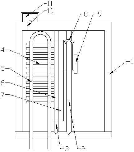
[0019] Such as figure 1 As shown, the present invention is a heat dissipation housing for meteorological monitoring equipment, including a housing main body, a partition plate is arranged in the housing main body, and the internal cavity of the housing main body is divided into an electrical component installation cavity and a heat dissipation cavity by the partition board. cavity, the partition plate is sealed and connected with the inner wall of the main body of the shell; a secondary partition plate is arranged in the heat dissipation cavity, and the heat dissipation cavity is divided into a heat exchange cavity and a water blocking cavity, wherein the wate...


PUM


Abstract

The invention relates to a heat radiation housing of meteorological monitoring equipment. The heat radiation housing comprises a housing body, and a partition plate arranged in the housing body, wherein the inner cavity of the housing body is separated into an electrical component mounting cavity and a heat radiating cavity through the partition plate. A sub-partition plate is arranged in the heat radiating cavity to divide the heat radiating cavity into a heat exchange cavity and a water blocking cavity, and a heat exchanger is arranged in the heat exchange cavity. The heat exchanger comprises a plurality of heat exchange fins which are connected with one another through a heat exchange coil. The water inlet and the water outlet of the heat exchange coil are extended to the outside of the housing body and are connected with a domestic water pipeline. The water blocking cavity is provided with a heat conduction plate, which passes through the sub-partition plate and of which the edges are in sealing connection with the sub-partition plate. A plurality of capillary heat conduction pipes are welded on the heat conduction plate, and extend into the electrical component mounting cavity after passing through the partition plate. Heat conduction heads are welded on the end portion of the electrical component mounting cavity corresponding to the capillary heat conduction pipes, and the heat exchange cavity is filled with heat exchange oil.

Description

technical field [0001] The invention relates to a heat dissipation shell of meteorological monitoring equipment, which belongs to the field of meteorological equipment. Background technique [0002] With the development of technology, meteorological monitoring equipment has developed from traditional instruments that need to be recorded manually to various types of sensor devices, and the convenience has been greatly improved. However, compared with instruments, the data of sensor devices cannot be directly read. Supporting related microcomputer equipment is converted and uploaded to the network, and various calculation formulas need to be simulated for data calculation. The amount of resources is large, and the load on the microcomputer is also high, especially in summer. The timely heat dissipation of the microcomputer can easily lead to the burning of the equipment, and in the case of high ambient temperature in summer, the use of forced airflow for heat exchange cannot m...

Claims


Application Information

Patent Timeline
IPC IPC(8): H05K5/02H05K7/20
CPCH05K5/0217H05K7/20218H05K7/20272
Inventor 禹胜林
Owner WUXI NUIST WEATHER SENSOR NETWORK TECH
Why Eureka
Try Eureka