Camshaft-adjusting device

A technology of camshaft adjustment and regulator, which is applied to valve devices, engine components, machines/engines, etc., and can solve problems such as the rotor not being locked on one side, high cost, and noise generation

Active Publication Date: 2016-12-14
SCHAEFFLER TECH AG & CO KG
View PDF7 Cites 4 Cited by
  • Summary
  • Abstract
  • Description
  • Claims
  • Application Information

AI Technical Summary

Problems solved by technology

[0004] The problem with such camshaft adjustments is that they may not yet be completely filled with pressure medium during the start-up phase, or may even run without load, so that the rotor may exert an uncontrolled movement relative to the stator due to the alternating torque exerted by the camshaft. Uncontrolled movements that may cause increased wear and may lead to undesired noise generation
[0006] The disadvantage of this solution is that the locking of the rotor can only be achieved with several locking pins which are locked one behind the other, which leads to higher costs
As long as one of the locking pins is not locked, the locking process is interrupted, since the rotor is thus not locked in the neutral position on one side and can again rotate again.

Method used


Image

  • Camshaft-adjusting device
  • Camshaft-adjusting device
  • Camshaft-adjusting device

Examples


Embodiment Construction

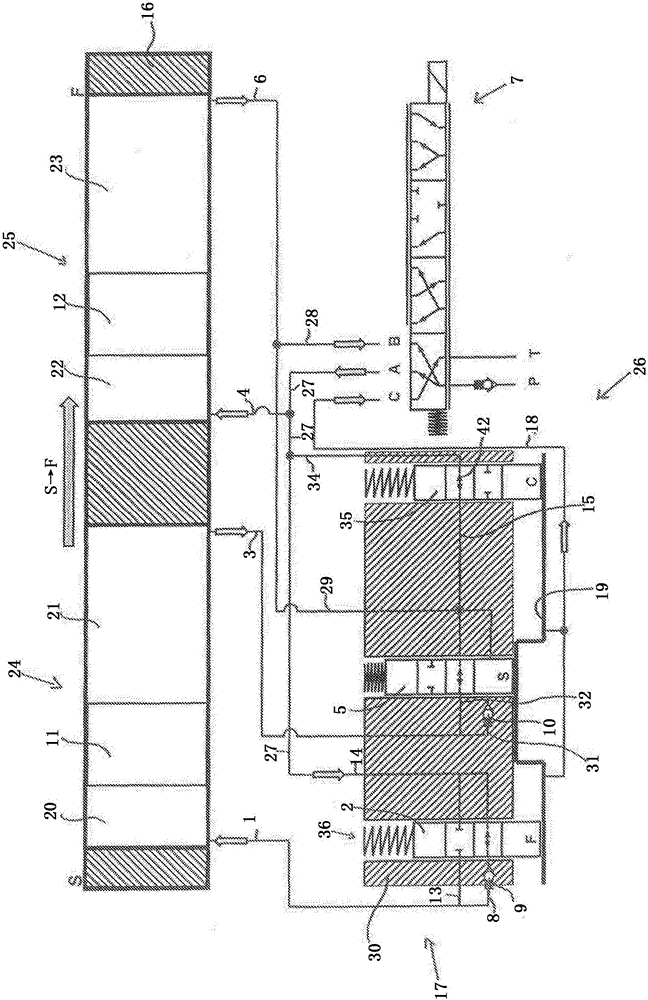
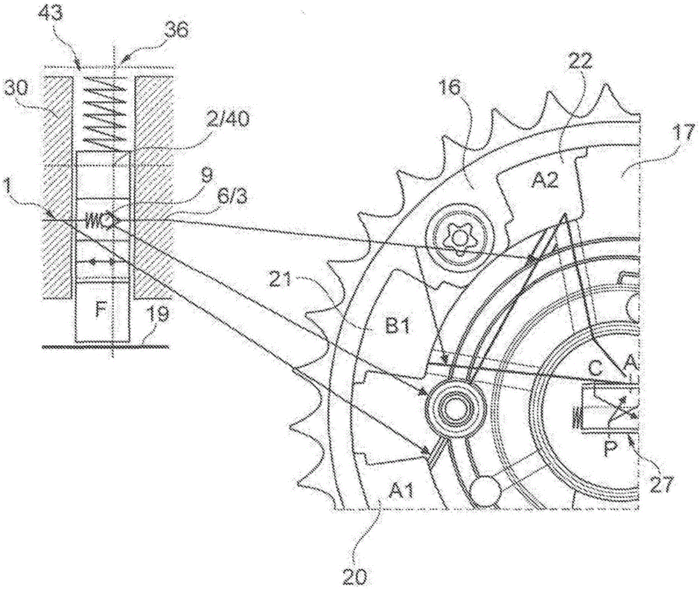
[0026] exist figure 1A camshaft adjusting device with a known basic structure can be seen in the figure, with a schematically shown vane chamber adjuster as a basic component, which comprises a stator 16 that can be driven by a crankshaft, not shown, and that can A rotor 17 , which is connected in a rotationally fixed manner to a camshaft, likewise not shown, has a plurality of vanes 11 and 12 extending radially outward from it. In the upper representation the vane chamber regulator can be seen unfolded, and at the bottom left schematically a section of the rotor 17 with the central locking device 26 can be seen, and at the bottom right the form can be seen schematically. is a switching device for controlling the pressure medium flow of the multi-way switching valve 7 . The multi-way switching valve 7 has an A port, a B port and a C port, to which the pressure medium lines 18 , 27 and 28 are fluidically connected. Furthermore, the multi-way switching valve 7 is fluidically c...


PUM


Abstract

The invention relates to a camshaft-adjusting device, comprising a vane cell adjuster having a stator (16) that can be connected to a crankshaft of an internal combustion engine and a rotor (17), which is rotatably supported in the stator (16) and which can be connected to a camshaft, wherein a plurality of webs are provided on the stator (16), which webs divide an annular space between the stator (16) and the rotor (17) into a plurality of pressure chambers (24, 25), wherein the rotor (17) has a rotor hub (30) and a plurality of vanes (11, 12) extending radially outward from the rotor hub (30), which vanes divide the pressure chambers (24, 25) into two groups of working chambers (20, 21, 22, 23) having a different acting direction, into each of which working chambers pressure medium flowing in or out in a pressure-medium circuit can be admitted, and a central locking device (26) for locking the rotor (17) in at least one locking position in relation to the stator (17), wherein the central locking device (26) has at least two spring-loaded locking pins (2, 5) in an accommodating space (43, 44), which locking pins can be locked in a locking slot (19) secured to the stator and lock in the locking slot (19) when the rotor (17) rotates from the direction of an "early" or "late" stop position into the locking position from different directions, wherein the locking pin (2, 5) forms a valve device (36, 37) together with the particular accommodating space (43, 44), wherein the locking pin (2, 5) forms a valve pin (40), wherein the valve pin (40) is a step pin.

Description

technical field [0001] The invention relates to a camshaft adjusting device having the features of the preamble of claim 1 . Background technique [0002] Camshaft adjustment devices are often used in valve trains of internal combustion engines in order to vary the opening and closing times of the valves, whereby the fuel consumption values ​​and the operating characteristics of the internal combustion engine can generally be improved. [0003] A proven embodiment of a camshaft adjusting device has a vane chamber adjuster with a stator and a rotor which delimit an annular space which is divided into a plurality of working chambers by means of projections and vanes. The working chambers can be selectively charged with pressure medium which is conveyed in a pressure medium circuit via a pressure medium pump from a pressure medium reservoir to the working chambers on one side of the rotor blades and from the corresponding other side of the blades. The working chamber on the si...

Claims


Application Information

Patent Timeline
Patent Type & Authority Applications(China)
IPC IPC(8): F01L1/344
CPCF01L1/3442F01L2001/34453F01L2001/34466F01L2001/34463F01L2001/34459F01L2001/34476
Inventor 托尔斯滕·奇尚斯特芬·拉克勒贝
Owner SCHAEFFLER TECH AG & CO KG
Why Eureka
Try Eureka