Surgical robot system
A technology of surgical robots and manipulators, applied in the field of medical equipment, can solve problems such as movement interference or difficulty in reaching the ideal position, and achieve the effects of simple structure, suppressing the possibility of collision, and small size
- Summary
- Abstract
- Description
- Claims
- Application Information
AI Technical Summary
Problems solved by technology
Method used
Image
Examples
Embodiment 1
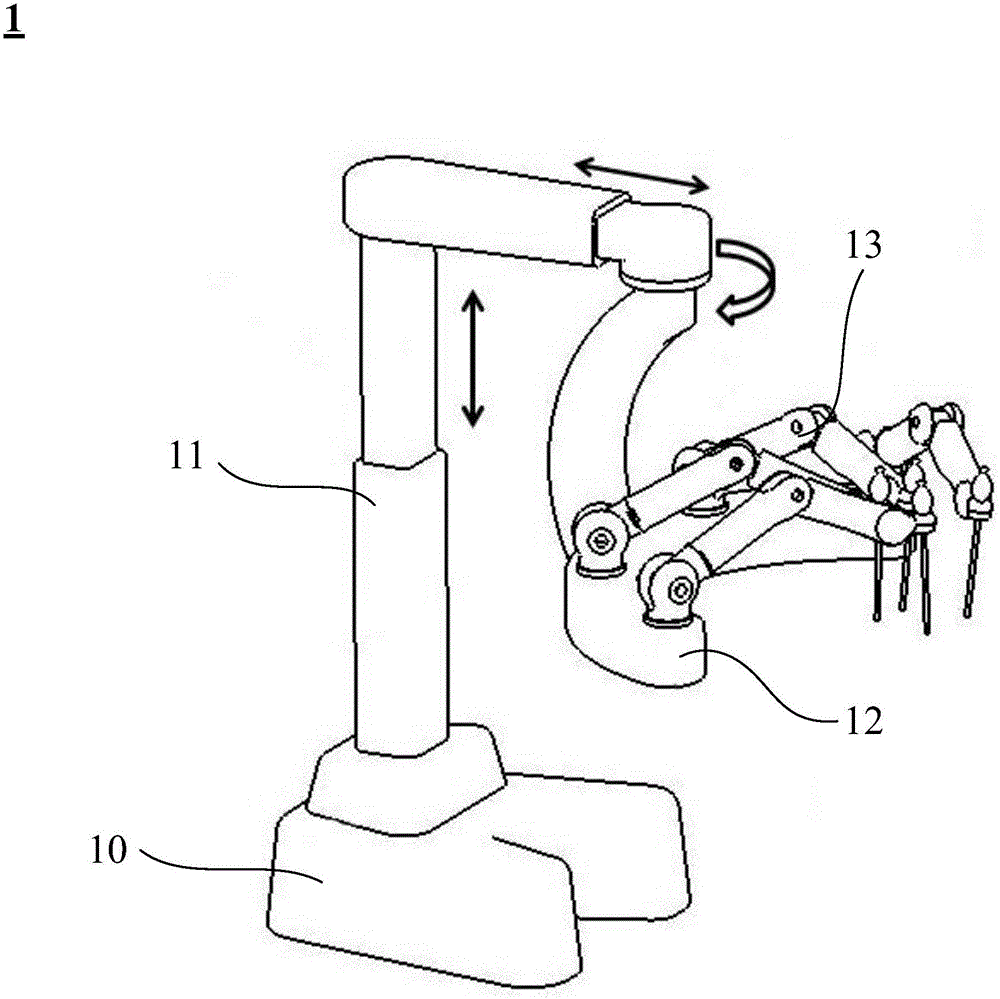
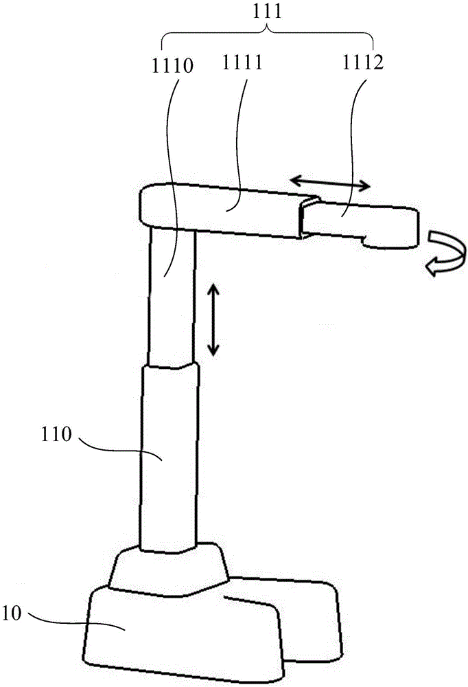
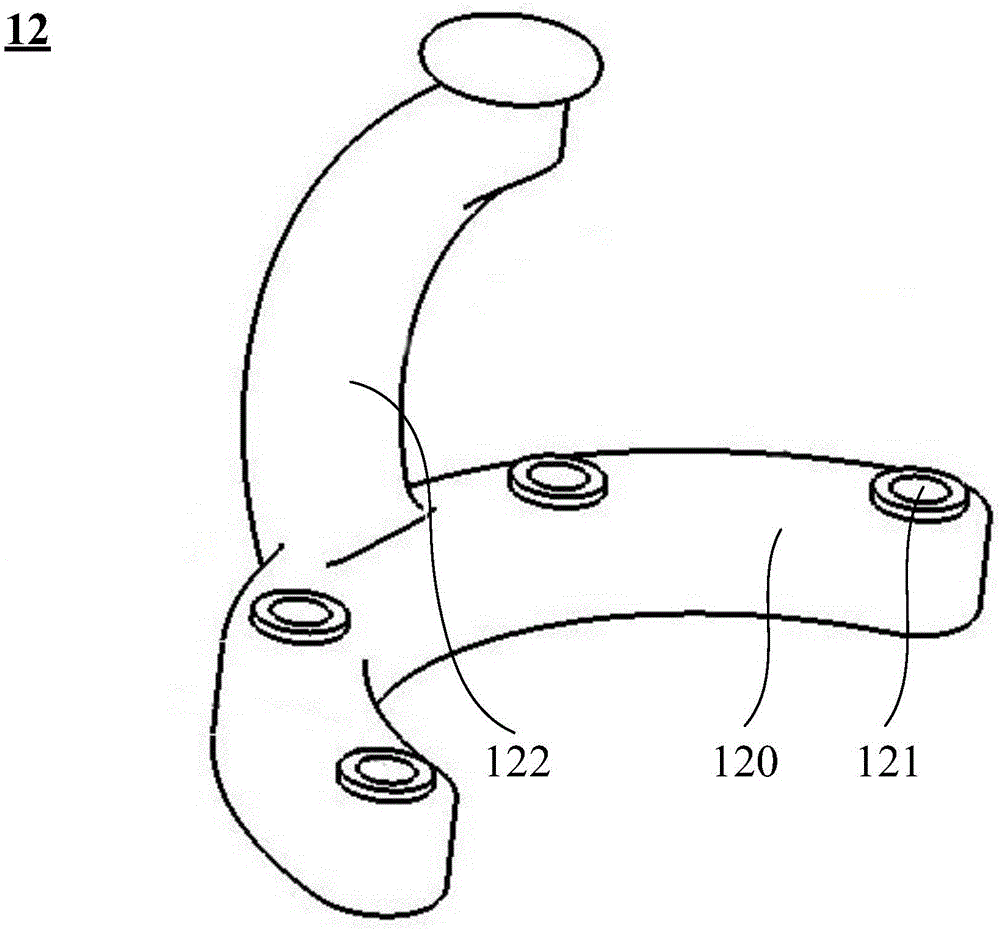
[0047] Please refer to Figure 1 to Figure 4 ,in, figure 1 It is a structural schematic diagram of the surgical robot system according to Embodiment 1 of the present invention; figure 2 It is a structural schematic diagram of the base structure and the supporting structure of Embodiment 1 of the present invention; image 3 It is a structural schematic diagram of the suspension structure of Embodiment 1 of the present invention; Figure 4 It is a structural schematic diagram of the manipulator structure of Embodiment 1 of the present invention.
[0048] Such as Figure 1 to Figure 4 As shown, in Embodiment 1 of the present application, the surgical robot system 1 includes: a modular structure (not shown) and a manipulator structure 13, the modular structure includes a base structure 10, and the base structure 10 connected The support structure 11 , the suspension structure 12 connected with the support structure 11 , the suspension structure 12 connected with the manipulat...
Embodiment 2
[0059] Please refer to Figure 6 , which is a structural schematic diagram of the base structure and the supporting structure of Embodiment 2 of the present invention. Such as Figure 6 As shown, in the embodiment of the present application, the support structure 21 includes a first support portion 210 fixed on the base structure 20 and a second support portion 211 connected to the first support portion 210, wherein the The second supporting part 211 can move along the extending direction of the first supporting part 210 . Further, the second support part 211 includes a first support subsection 2110 connected to the first support part 210, a second support subsection 2111 connected to the first support subsection 2110, and a second support subsection 2111 connected to the first support subsection 2110. The third support subsection 2112 connected by the two support subsections 2111 , wherein the extension directions of the first support subsection 2110 and the third support s...
Embodiment 3
[0063] Please refer to Figure 7 , which is a structural schematic diagram of the base structure and the supporting structure of Embodiment 3 of the present invention. Such as Figure 7 As shown, in the embodiment of the present application, the support structure 31 includes a first support portion 310 fixed on the base structure 30 and a second support portion 311 connected to the first support portion 310 . Further, the second support part 311 includes a first support subsection 3110 that is movably connected with the first support part 310, a second support subsection 3111 that is fixedly connected with the first support subsection 3110, and a The second supporting subsection 3111 is fixedly connected to the third supporting subsection 3112, and the extension directions of the first supporting subsection 3110 and the third supporting subsection 3112 are perpendicular to each other. Preferably, the included angle between the second support subsection 3111 and the first sup...
PUM
 Abstract
Description
Claims
Application Information
 - R&D
- Intellectual Property
- Life Sciences
- Materials
- Tech Scout
- Unparalleled Data Quality
- Higher Quality Content
- 60% Fewer Hallucinations
Browse by: Latest US Patents, China's latest patents, Technical Efficacy Thesaurus, Application Domain, Technology Topic, Popular Technical Reports.
© 2025 PatSnap. All rights reserved.Legal|Privacy policy|Modern Slavery Act Transparency Statement|Sitemap|About US| Contact US: help@patsnap.com


