A single shaft shredder

A shredder, single-shaft technology, used in grain processing and other directions, can solve the problems of easy overheating of the cutter shaft and movable knife, insufficient cutting force, and high energy consumption of the cutter roller, so as to reduce temperature, large cutting force, and energy consumption. reduced effect

Active Publication Date: 2018-07-31
GENOX RECYCLING TECH +1
View PDF6 Cites 0 Cited by
  • Summary
  • Abstract
  • Description
  • Claims
  • Application Information

AI Technical Summary

Problems solved by technology

However, the existing movable knives are usually welded on the cutter shaft, which is not easy to replace; and the cutting force is not enough, and it is easy to be damaged by the impact of the material when crushing the material with high hardness, and the entire cutter roller consumes a lot of energy; in addition, In the process of continuous rotation of the knife shaft, the knife shaft and the moving knife will be easily overheated, resulting in fast wear of the moving knife; and the crushing efficiency is low

Method used


Image

  • A single shaft shredder
  • A single shaft shredder
  • A single shaft shredder

Examples


Embodiment Construction

[0031] Below, in conjunction with accompanying drawing and specific embodiment, the present invention is described further:

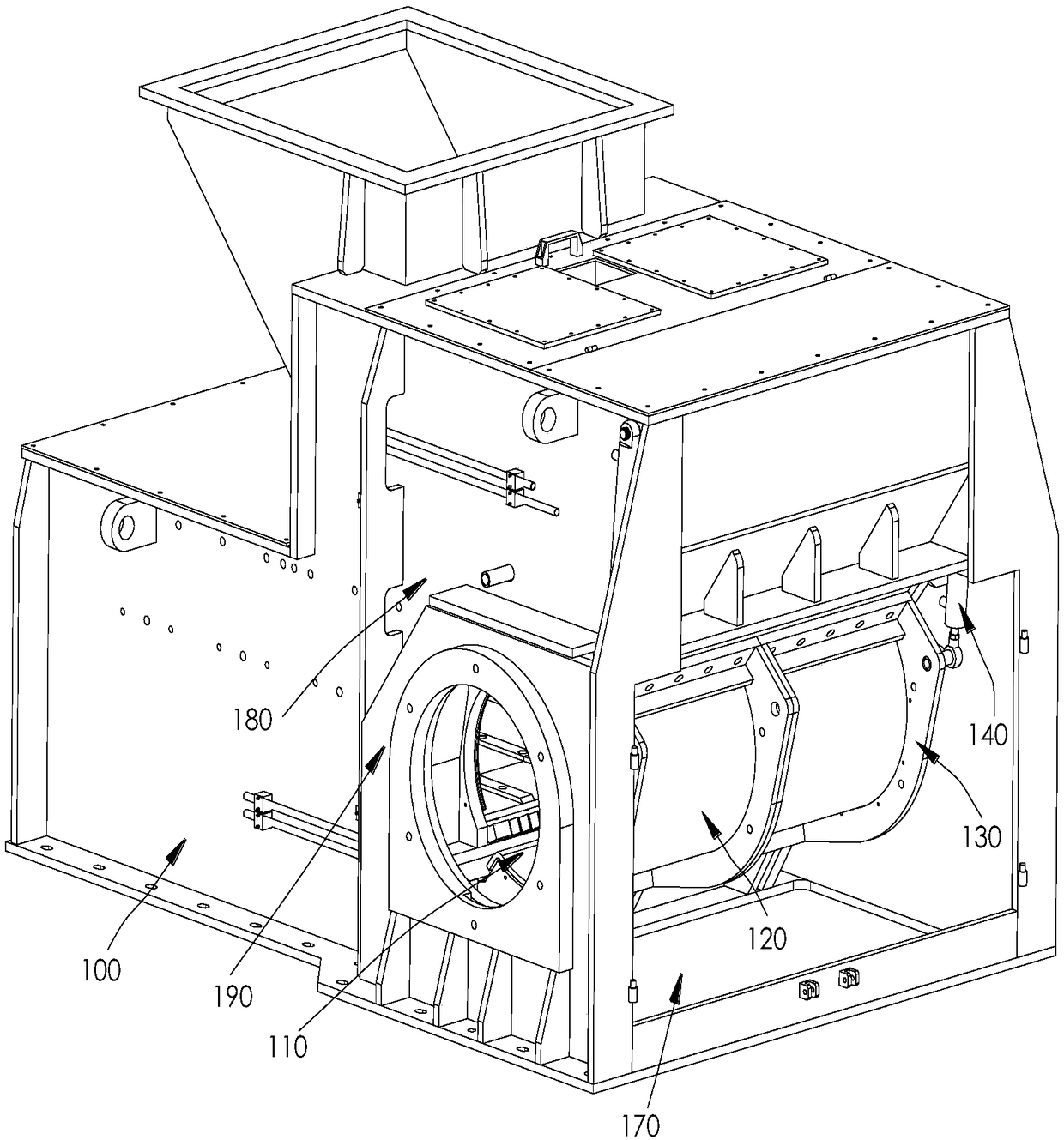
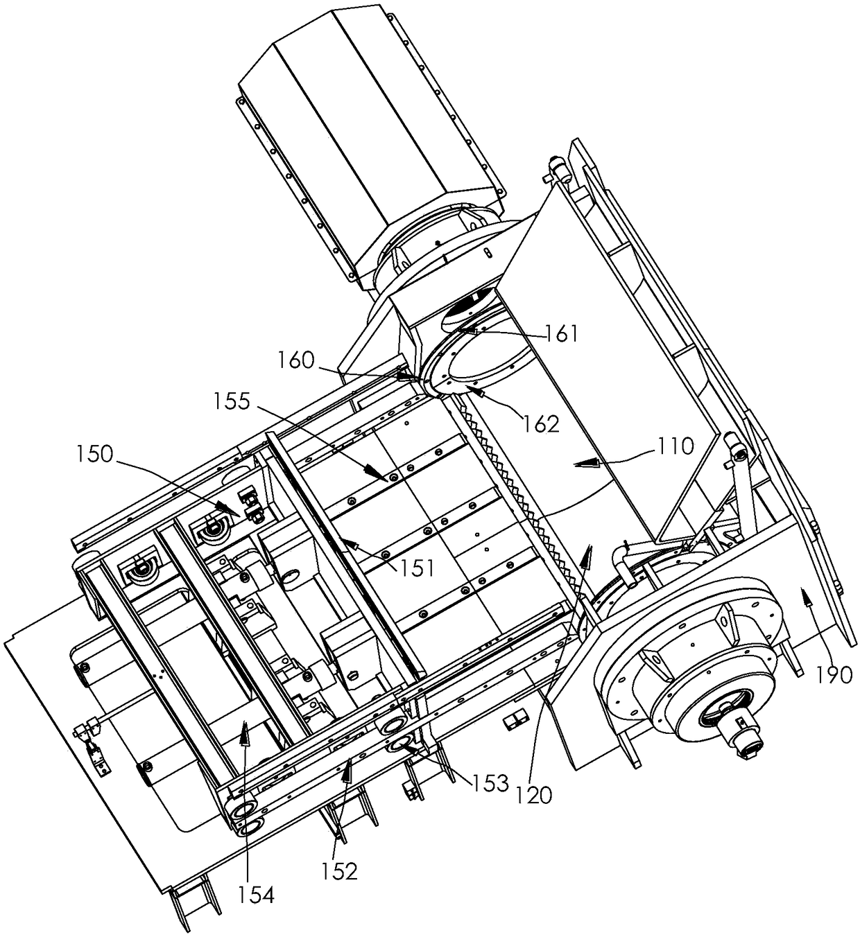
[0032] Such as Figure 1-9 The single-shaft shredder shown includes a box body 100, a pushing mechanism 150, a knife shaft 210, a plurality of moving knives 220 and a fixed knife 230, and a crushing cavity 110 is formed at one end of the box body 100, and the pushing mechanism 150 is located at the end of the box body 100 away from the crushing chamber 110, and the above-mentioned cutter shaft 210 is pivotally connected in the crushing chamber 110, and a water cooling chamber 213 is formed inside the cutter shaft 210, and a plurality of In the first installation slot, a plurality of movable knives 220 can be installed in the plurality of first installation slots in a one-to-one correspondence. The fixed knife 230 is fixed on one side of the crushing cavity 110 and is located on the side of the crushing cavity 110 close to the pushing mechanism 150 , an...


PUM


Abstract

The invention discloses a single-shaft shredder comprising a box body, a pushing mechanism, a cutter shaft, a plurality of moving cutters and a fixed cutter; a crushing cavity is formed at one end of the box body; the pushing mechanism is arranged at the end, far away from the crushing cavity, of the box body; the cutter shaft is pivoted in the crushing cavity, and a water cooling cavity is formed inside the cutter shaft; a plurality first mounting slots are formed in the surface of the outer circumference of the cutter shaft; each moving cutter comprises a cutter seat and a cutting edge, and the cutter seat of each moving cutter is mounted in each of the first mounting slots; the cutting edge is connected to the cutter seat; the cutting edge is provided with a first cutting line, a second cutting line and a discharging groove, the first cutting line and the second cutting line are respectively formed at two sides of the cutting edge, and the first cutting line is located in front of the second cutting line in the rotating direction of the cutter shaft; the discharging groove is formed between the first cutting line and the second cutting line and communicates to the end surfaces at two sides of the cutting edge; and the fixed cutter is fixedly arranged at one side of the crushing cavity and is spaced from the surface of the outer circumference of the cutter shaft to form a cutting gap. The single-shaft shredder is strong in power cutting force, convenient to mount and high in crushing efficiency.

Description

technical field [0001] The invention relates to the technical field of material processing equipment, in particular to a single-shaft shredder. Background technique [0002] Single-shaft shredder refers to a shredder with a single knife roller. There are multiple moving knives fixed on the knife shaft, and fixed knives are fixed in the corresponding box. When the driving mechanism drives the knife roller to rotate, the movement of the knife shaft The knife rotates around the central axis of the knife shaft. During the rotation of the moving knife, the blade of the moving knife will cut the material together with the blade of the fixed knife and tear the material into pieces. However, the existing movable knives are usually welded on the cutter shaft, which is not easy to replace; and the cutting force is not enough, and it is easy to be damaged by the impact of the material when crushing the material with high hardness, and the entire cutter roller consumes a lot of energy; ...

Claims


Application Information

Patent Timeline
Patent Type & Authority Patents(China)
IPC IPC(8): B02C18/14B02C18/18B02C18/22B02C18/16
CPCB02C18/14B02C18/16B02C18/18B02C18/2233B02C2018/162
Inventor 蒋经发
Owner GENOX RECYCLING TECH
Why Eureka
Try Eureka