Fluid injection area light source indicating and positioning device

A technology of fluid injection and positioning device, applied in the direction of injection device, etc., can solve the problem of difficulty in accurately monitoring the cooling medium injection area, etc., and achieve the effect of precise control and easy adjustment.

Pending Publication Date: 2016-12-21
SHANDONG UNIV
View PDF6 Cites 3 Cited by
  • Summary
  • Abstract
  • Description
  • Claims
  • Application Information

AI Technical Summary

Problems solved by technology

[0005] The purpose of the present invention is to provide a fluid injection area light source indication and positioning device to solve the problem that it is difficult to accurately monitor the actual injection area of ​​the cooling medium in MQL technology

Method used


Image

  • Fluid injection area light source indicating and positioning device
  • Fluid injection area light source indicating and positioning device
  • Fluid injection area light source indicating and positioning device

Examples


Embodiment 1

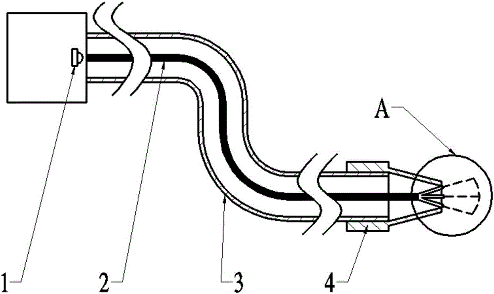
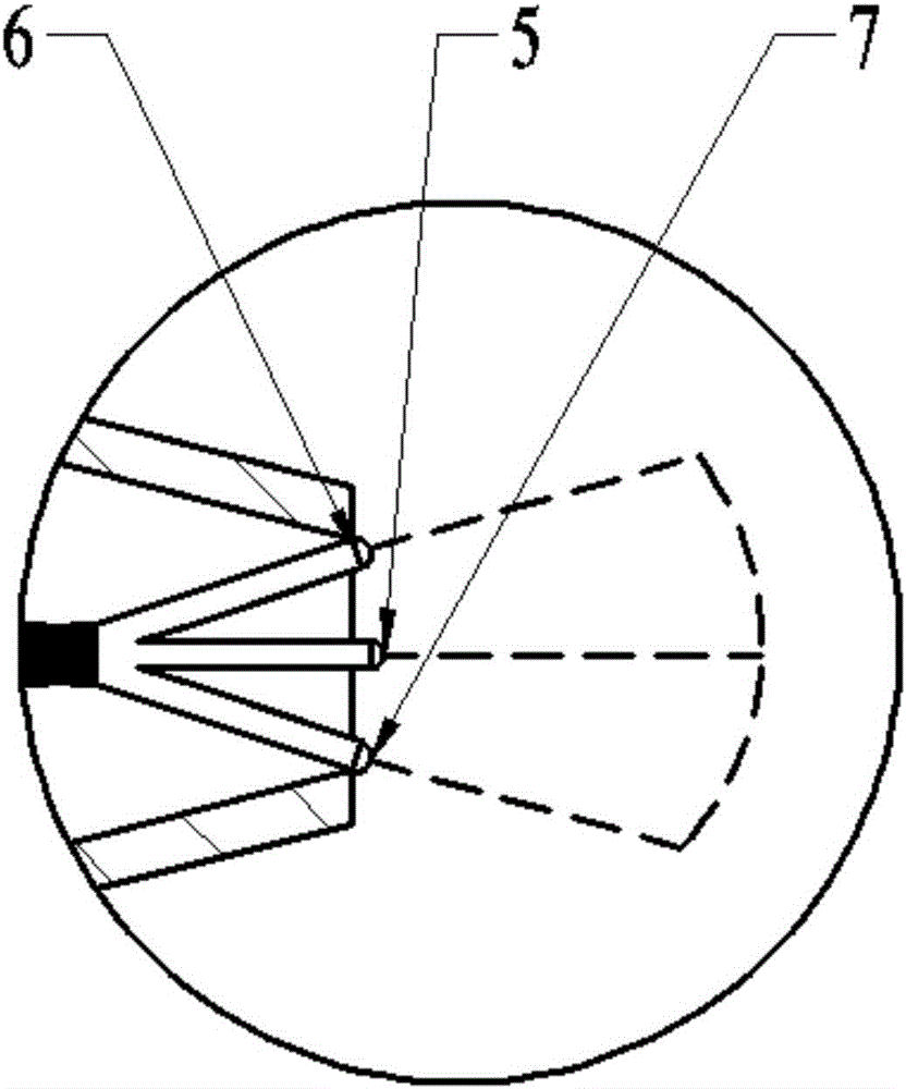
[0019] The light source in this embodiment indicates the positioning device, such as figure 1 As shown, it mainly includes a light source 1, a light guide 2, a flexible nozzle 3, a nozzle 4, a first daylighting cover 5, a second daylighting cover 6 and a third daylighting cover 7. The light source 1 is placed at one end of the flexible nozzle 3 , the light guide 2 is placed inside the flexible nozzle 3 , and the other end of the flexible nozzle 3 is provided with a nozzle 4 . see figure 2 , the light guide 2 is provided with a first daylighting cover 5, a second daylighting cover 6 and a third daylighting cover 7 at the nozzle 4. Wherein, the first daylighting cover 5 is positioned at the center line of nozzle 4, as positioning light emitter; Indicating light emitters.

[0020] The light source 1 emits light, which is transmitted to the first lighting cover 5 , the second lighting cover 6 and the third lighting cover 7 located at the nozzle 4 through the light guide 2 plac...

Embodiment 2

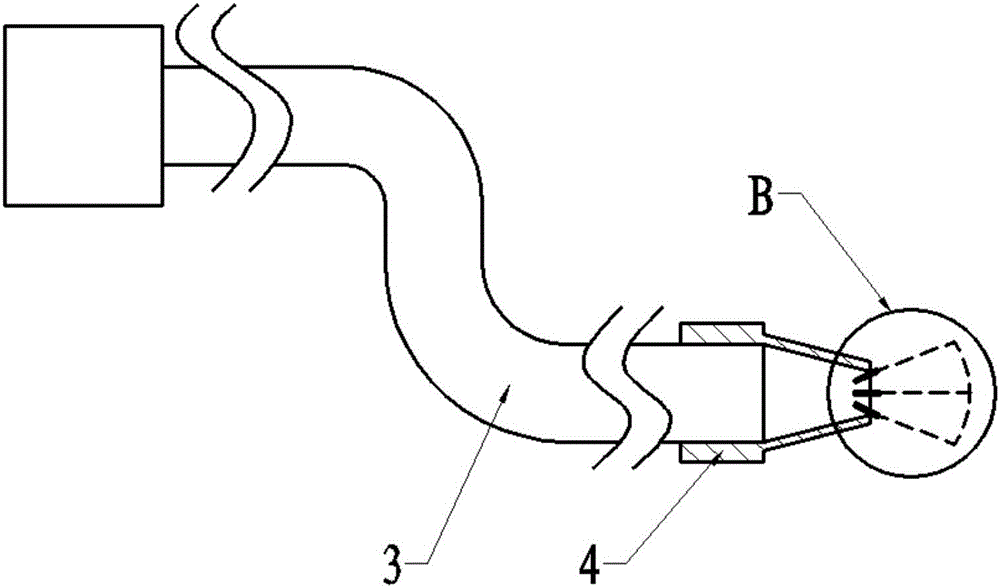
[0022] Such as image 3 As shown, the difference between this embodiment and the first embodiment is that the light in this embodiment does not need to be emitted by the light source and transmitted by the light guide, there is no light guide 2 in the flexible nozzle 3, and only three laser emitters are arranged on the inner wall of the nozzle 4 devices, that is, the first laser emitter 8 , the second laser emitter 9 and the third laser emitter 10 . All laser transmitters used have built-in power supply and can emit light directly. Wherein, the first laser emitter 8 is located on the center line of the nozzle 4, and serves as a light emitter for positioning, and the emitted light is accurately directed to the position that the cooling medium can reach. The second laser emitter 9 and the third laser emitter 10 are respectively located on the upper and lower sides or the left and right sides of the first laser emitter 8, as the light emitter for range indication, and the first ...


PUM


Abstract

The invention provides a fluid injection area light source indicating and positioning device. The fluid injection area light source indicating and positioning device comprises a flexible injection pipe and a nozzle. The nozzle is arranged at one end of the flexible injection pipe and internally provided with a positioning light ray emitter and two range indicating light ray emitters. The positioning light ray emitter is located in the center of the nozzle. The two range indicating light ray emitters are located on the two sides of the positioning light ray emitter correspondingly. According to the fluid injection area light source indicating and positioning device, the positioning light ray emitter emits a light beam, and the indicated position is an actual working area where an injection medium can reach; the two range indicating light ray emitters emit light beams in the injection direction of a cooling medium, and the area formed between the two light beams is the range where the cooling medium can reach during actual processing; and the injection range, including the injection angle and the injection distance, of the cooling medium during injection is simulated by means of the light beams, so that the working area of the cooling medium is completely monitored, correct adjusting of the injection position and pose is facilitated, and precise control over the injection device position and pose can be achieved.

Description

technical field [0001] The invention relates to a device for indicating a light source to a fluid injection area so as to locate the injection position, and belongs to the technical field of light source positioning. Background technique [0002] In recent years, in order to improve the processing efficiency and quality of difficult-to-machine materials, prolong tool life and reduce the amount of cutting fluid, minimum quantity lubrication technology (MQL) has been more and more widely used. MQL technology mixes the compressed gas and a very small amount of lubricating liquid to vaporize, and then sprays it to the workpiece processing area through the nozzle to effectively lubricate the processing part between the tool and the workpiece. [0003] However, the use of MQL technology still has its limitations: the range of MQL cooling and lubrication is small, and the cooling medium must be accurately sprayed to the current cutting part of the tool, otherwise the expected cooli...

Claims


Application Information

Patent Timeline
Patent Type & Authority Applications(China)
IPC IPC(8): B05B15/08B05B15/68
CPCB05B15/68
Inventor 国凯魏鑫孙杰李卫东宋戈孙超
Owner SHANDONG UNIV
Why Eureka
Try Eureka