
Latticed shell structure and wind-resistant truss column connection structure

A technology for connecting structures and reticulated shells, which is applied in the direction of building structure and construction, can solve the problems of not being able to adapt well to the strong wind environment and inconvenient construction, and achieve the effects of easy reconstruction and expansion, simple form, and low construction difficulty

Active Publication Date: 2016-12-21
HUATIAN ENG & TECH CORP MCC
View PDF5 Cites 2 Cited by
  • Summary
  • Abstract
  • Description
  • Claims
  • Application Information

AI Technical Summary

Problems solved by technology

[0002] At present, the spatial grid structure has been widely used in public infrastructure such as industrial plants, railway stations and bus stations. However, there are still the following problems about the connection node structure between the wind-resistant truss of the gable and the spatial grid structure: the wind-resistant truss During the installation and construction of the space grid structure, due to the difference in the relative positions of the connecting node structures, the construction is inconvenient, and the wind-resistant truss and the space grid structure after installation and construction cannot well adapt to the strong wind environment

Method used


Image

  • Latticed shell structure and wind-resistant truss column connection structure
  • Latticed shell structure and wind-resistant truss column connection structure
  • Latticed shell structure and wind-resistant truss column connection structure

Examples


Embodiment Construction

[0030] The present invention will be described in detail below in conjunction with the implementations shown in the drawings, but it should be noted that these implementations are not limitations of the present invention, and those of ordinary skill in the art based on the functions, methods, or structural changes made by these implementations Equivalent transformations or substitutions all fall within the protection scope of the present invention.

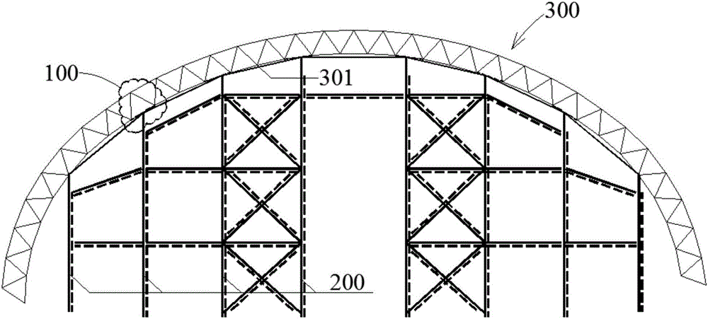
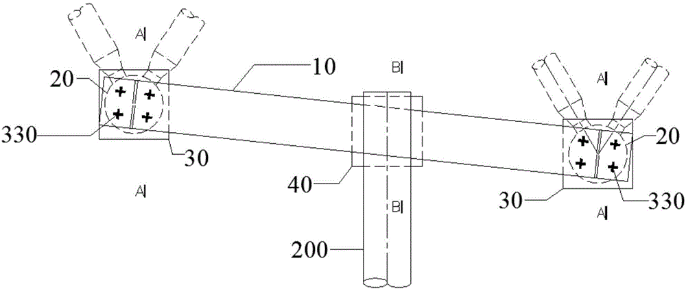
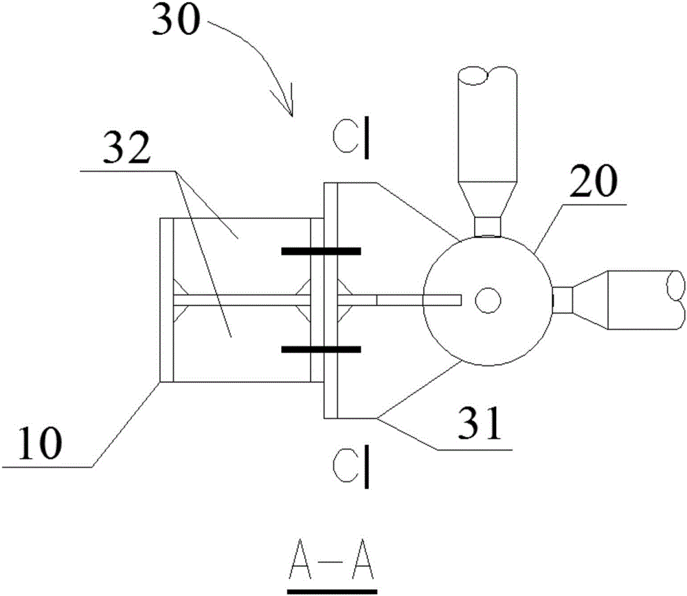
[0031] Such as figure 1 , 2 As shown, the connection structure 100 between the reticulated shell structure 300 and the wind-resistant truss column 200 of the present invention includes: a horizontal steel beam 10 , a reticulated shell bottom chord node 20 , a first connecting component 30 , and a second connecting component 40 .

[0032] Wherein, the reticulated shell structure has a reticulated shell lower chord layer 301, and the reticulated shell lower chord ball nodes 20 are several, and several reticulated shell lower chord ...


PUM


Abstract

The invention provides a latticed shell structure and wind-resistant truss column connection structure, comprising a horizontal steel beam, a latticed shell lower chord ball joint, a first connection component and a second connection component; the latticed shell lower chord ball joint is mounted on a latticed shell lower chord layer of a latticed shell structure and is connected with the horizontal steel beam through the first connection component, the horizontal steel beam is connected with the wind-resistant truss column through the second connection component, the first connection component comprises a first connector and a second connector connected with each other, the first connector is provided with a vertical elliptical hole, the second connector is provided with a round bolt hole, the second connection component comprises a third connector and a fourth connector connected with each other, the third connector is provided with a horizontal transverse elliptical hole, and the fourth connector is provided with a vertical elliptical hole. The connection structure of the invention has the advantages of simple form, clear force transmission path, good safety and reliability, reduced joint construction difficulty and facilitated late reformation and extension.

Description

technical field [0001] The invention relates to the technical field of installation and construction of a reticulated shell structure and a wind-resistant truss, in particular to a connection structure between a reticulated shell structure and a wind-resistant truss column. Background technique [0002] At present, the spatial grid structure has been widely used in public infrastructure such as industrial plants, railway stations and bus stations. However, there are still the following problems about the connection node structure between the wind-resistant truss of the gable and the spatial grid structure: the wind-resistant truss During the installation and construction of the space grid structure, due to the difference in the relative positions of the connecting node structures, the construction is inconvenient, and the wind-resistant truss and the space grid structure after installation and construction cannot well adapt to the strong wind environment. [0003] Therefore,...

Claims


Application Information

Patent Timeline
Patent Type & Authority Applications(China)
IPC IPC(8): E04B1/19E04B1/58
CPCE04B1/19E04B1/1906E04B2001/1963
Inventor 傅强
Owner HUATIAN ENG & TECH CORP MCC
Learn More