
a car stop

A car-blocking, one-to-one technology, applied in the field of car-stopping devices, can solve the problems of not being able to block the tires, bumping into objects behind the car, and prone to danger, etc., and achieve the effect of realizing the car-stopping function, low cost, and good car-blocking effect

Active Publication Date: 2018-10-02
江苏蒎圣屋工业科技有限公司
View PDF7 Cites 0 Cited by
  • Summary
  • Abstract
  • Description
  • Claims
  • Application Information

AI Technical Summary

Problems solved by technology

Since the car stop is used to limit the movement of the wheels, and the height of the chassis or fenders of many cars is relatively low, in order to improve the versatility, the height of most car stops is relatively low, which makes it easy for the tires of large vehicles to wear directly. The over-blocking device will not only fail to block the tires, but also easily cause danger; because the existing car-stopping device is an integrated solid structure, if the volume of the existing car-stopping device is directly enlarged, the cost will be relatively high. high, and very inconvenient to install
[0003] The Chinese patent document whose patent number is CN200620137046.9 discloses a kind of "moveable car stopper". This kind of wheel stopper is manually adjusted in height. It is possible to pass through the car stopper directly, but the disadvantage is that it is necessary to manually fix the position of the wheel stopper, which is troublesome to operate, and because it is put into the ground when not in use, it is easy to forget to pull it out when it is used again, causing the wheel to pass directly When the wheel chock hits an object behind the vehicle

Method used


Image

  • a car stop
  • a car stop
  • a car stop

Examples


Embodiment 1

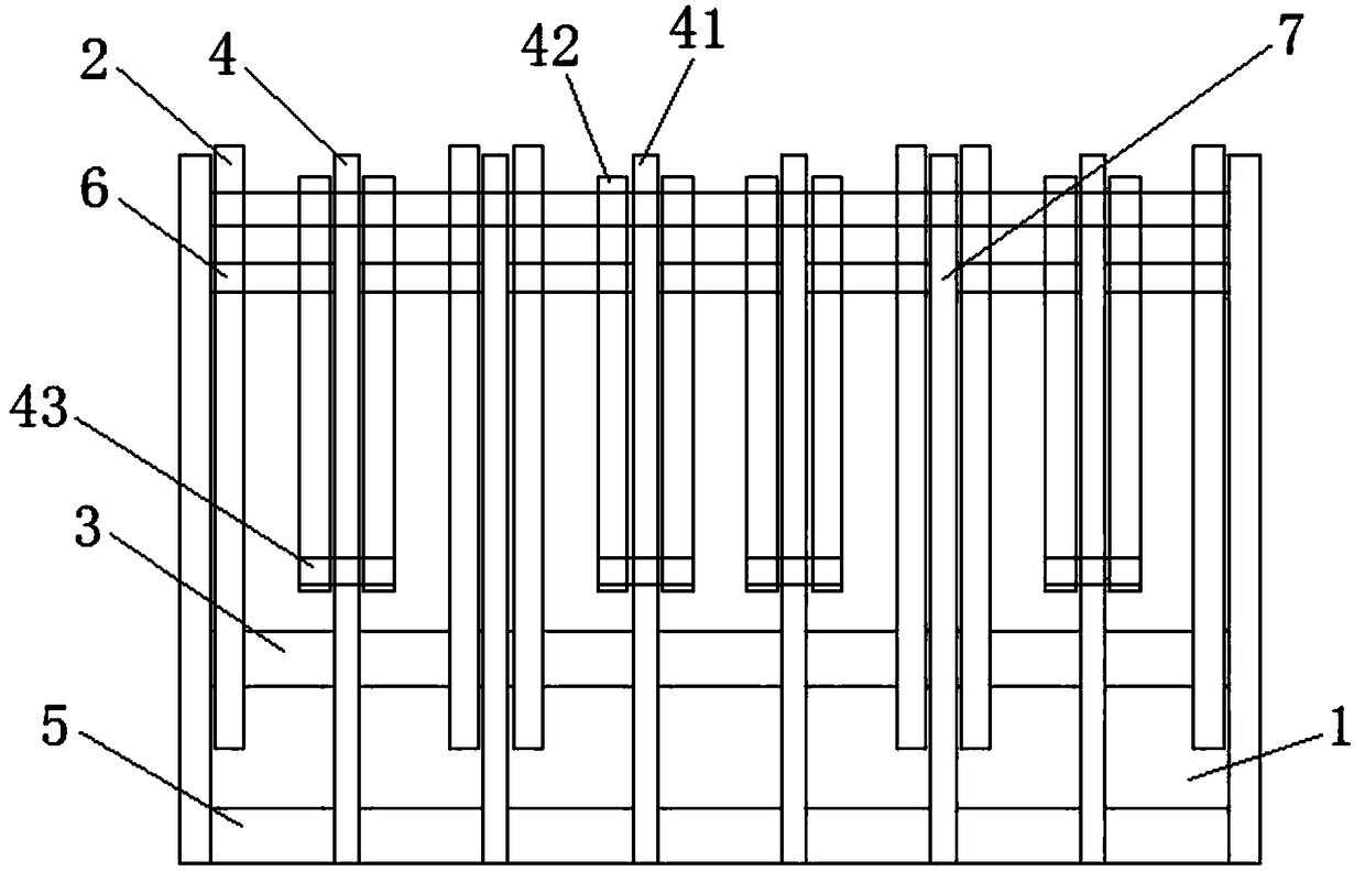
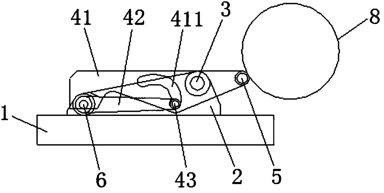
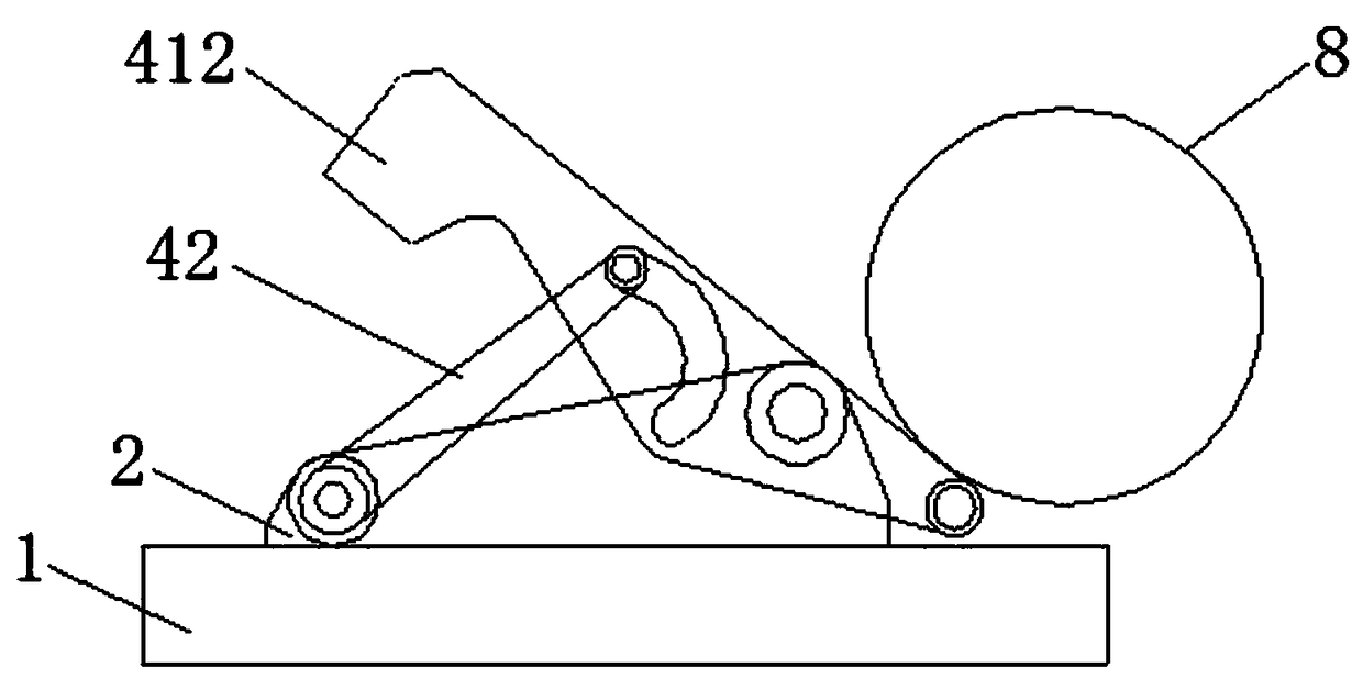
[0016] See Figure 1 to Figure 3 , the car blocking device of this embodiment includes a base 1 , a base plate 2 , a support shaft 3 , a car blocking unit 4 , a first connecting shaft 5 , a second connecting shaft 6 and a second baffle plate 7 .

[0017] At least one pair of base plates 2 are arranged side by side on the base 1. The upper front end and the rear end of the base plate 2 are respectively connected to the support shaft 3 and the second connecting shaft 6. A pair of car stop units is arranged between each pair of base plates 2. 4. The car blocking unit 4 includes a first baffle plate 41, connecting rods 42 positioned on both sides of the first baffle plate 41, and locking pins 43 connecting the front ends of the connecting rods 42 on both sides. All the first baffle plates 41 of the car blocking unit 4 The front ends are all connected to the first connecting shaft 5 , and the rear ends of the connecting rods 42 of all the stop units 4 are hinged to the second conn...


PUM


Abstract

The invention discloses a car stopper. The car stopper comprises a base, base plates, a support shaft, car stopping units, a first connecting shaft and a second connecting shaft, wherein at least a pair of base plates is arranged on the base side by side pairwise, and the upper parts of the front ends and the rear end parts of the base plates are connected onto the support shaft and the second connecting shaft respectively; each car stopping unit is arranged between the base plates in each pair and comprises a first stopping plate, connecting rods located on two sides of the first stopping plate and a locking pin connected with front end parts of the connecting rods on two sides; the front end parts of the first stopping plates of all the car stopping units are connected with the first connecting shaft, and the rear end parts of the connecting rods of all the car stopping units are all hinged with the second connecting shaft; a crescent through hole chute glidingly connected with the corresponding locking pin is arranged in the middle of each first stopping plate; the part between the front end part of each first stopping plate and the corresponding through hole chute is rotationally connected with the support shaft. The car stopper is simple in structure, convenient to mount, low in cost and good in car stopping effect and is particularly applicable to parking of oversize vehicles.

Description

technical field [0001] The invention relates to a vehicle blocking device. Background technique [0002] In parking lots and garages, in order to make the vehicle park accurately and neatly in the parking space when the vehicle is parked, and avoid colliding with other vehicles or scratching the car, so that the car is better protected, a car stop device is generally installed. Since the car stop is used to limit the movement of the wheels, and the height of the chassis or fenders of many cars is relatively low, in order to improve the versatility, the height of most car stops is relatively low, which makes it easy for the tires of large vehicles to wear directly. The over-blocking device will not only fail to block the tires, but also easily cause danger; because the existing car-stopping device is an integrated solid structure, if the volume of the existing car-stopping device is directly enlarged, the cost will be relatively high. High and very inconvenient to install. ...

Claims


Application Information

Patent Timeline
Patent Type & Authority Patents(China)
IPC IPC(8): E04H6/42
CPCE04H6/42
Inventor 何曣蔡健臣张长春
Owner 江苏蒎圣屋工业科技有限公司
Learn More