Array float-type wave power generation device

A power generation device and wave energy technology, which is applied to ocean energy power generation, engine components, machines/engines, etc., can solve the problems of inconvenient operation and maintenance, oil pollution of marine water bodies, high manufacturing cost, etc. The effect of energy utilization and low manufacturing cost

Inactive Publication Date: 2016-12-21
SHANGHAI OCEAN UNIV
View PDF8 Cites 0 Cited by
  • Summary
  • Abstract
  • Description
  • Claims
  • Application Information

AI Technical Summary

Problems solved by technology

The energy consumption of thermal power is high, the scale of hydropower is large, solar power is both limited and polluting, and wind power has poor adaptability. In short, the various forms of power generation mentioned above can only be used as interdependence to overcome the current shortage of resources
At present, the power generation of wave energy has also attracted people's attention. The existing wave energy power generation devices have complex structures, high manufacturing costs, inconvenient and expensive operation and maintenance, and at the same time, oily dirt will pollute marine water bodies.

Method used


Image

  • Array float-type wave power generation device
  • Array float-type wave power generation device
  • Array float-type wave power generation device

Examples


Embodiment Construction

[0023] The array buoy type wave energy generating device of the present invention will be further described in detail below with reference to the accompanying drawings.

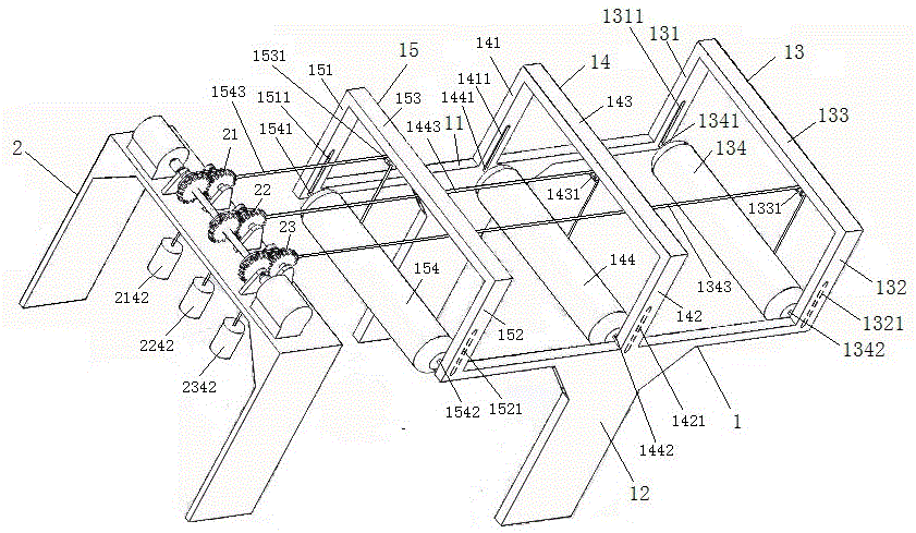
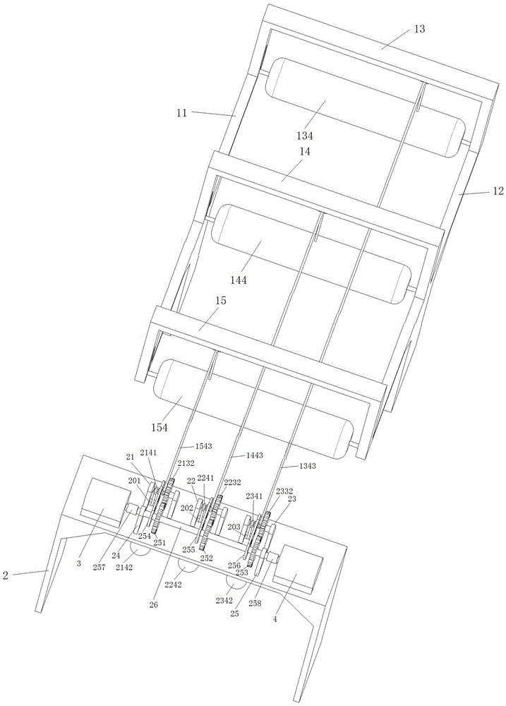
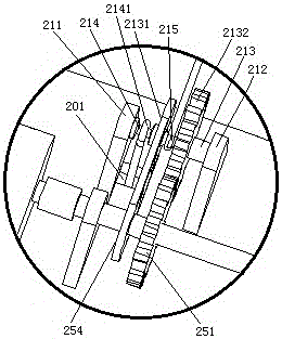
[0024] see figure 1 , figure 2 , image 3 , Figure 4 and Figure 5 , the array buoy type wave energy generating device of the invention includes a generating device body, and the generating device body is formed by a front frame 1 and a rear frame 2 .

[0025]Described front frame 1 is formed by left and right support seat 11,12 and the front support 13 that is distributed on left and right support seat 11,12, middle support 14 and rear support 15. The left and right bracket seats 11, 12 are in the shape of a "T", the front bracket 13, the middle bracket 14 and the rear bracket 15 are in the shape of an inverted groove, and the front bracket 13 in the shape of an inverted groove is all in the shape of an inverted groove. , the middle bracket 14 and the rear bracket 15 bridge over the upper end surfaces...


PUM


Abstract

The invention discloses an array float-type wave power generation device. The array float-type wave power generation device is characterized in that a power generation device body is composed of a front rack and a rear rack; the front rack is formed by a front support, a middle support and a rear support which are distributed on a left support base and a right support base; the front support, the middle support and the rear support are all composed of left vertical rods, right vertical rods and cross beams with pulleys; left vertical sliding grooves and right vertical sliding grooves which are in sliding connection with short shafts on the two side faces of transverse float bowls are formed in the lower ends of the inner walls of the left vertical rods and the right vertical rods; transmission parts are distributed at the front end of the rear rack; the transmission parts are composed of chain wheels, gears, left wheel hubs and right wheel hubs, the chain wheels and the gears are arranged on transmission shafts located between left bearing pedestals and right bearing pedestals, and the left wheel hubs and the right wheel hubs are arranged at the two sides of the corresponding chain wheels; rope chains with the other ends penetrating through rope chain holes to be connected with heavy objects are wound on the left wheel hubs, and bearing pedestals fixedly connected with a spindle are arranged at the rear end of the rear rack; a gear A with a chain wheel a, a gear B with a chain wheel b and a gear C with a chain wheel c are distributed on the spindle; the spindle is fixed to a left generator output shaft and a right generator output shaft through a left coupling and a right coupling; and the transverse float bowls are connected with, and the other ends of the rope chains penetrate through the pulleys and then are wound on the right wheel hubs. The array float-type wave power generation device is used for coastal waters.

Description

technical field [0001] The invention relates to a power generation device, in particular to an array buoy type wave energy power generation device. Background technique [0002] With the development of science and technology, especially the rapid development of the manufacturing industry, the power consumption of industry, agriculture, roads, transportation and households is increasing. How to deal with it has become a top priority. Thermal power consumes a lot of energy, hydropower has a large scale, solar power is both limited and polluting, and wind power has poor adaptability. In short, the various forms of power generation mentioned above can only be used as interdependence to overcome the current shortage of resources. At present, the power generation of wave energy has also attracted people's attention. The existing wave energy power generation devices have complex structures, high manufacturing costs, inconvenient operation and maintenance, and high costs. Contents...

Claims


Application Information

Patent Timeline
Patent Type & Authority Applications(China)
IPC IPC(8): F03B13/18
CPCF03B13/185Y02E10/30
Inventor 訾丹丹邹伟孔芳王世明孔龙李亚美高振帮吴帅桥顾亚军汪义
Owner SHANGHAI OCEAN UNIV
Why Eureka
Try Eureka