Fault detection circuit of direct current fans
A fault detection circuit, DC fan technology, applied in non-varactor pump, pump control, machine/engine and other directions, can solve the problems of high power density of charging pile power module, DC fan failure, affecting normal operation, etc. The cost of components is low, the fault detection is convenient, and the effect of avoiding malfunction
- Summary
- Abstract
- Description
- Claims
- Application Information
AI Technical Summary
Problems solved by technology
Method used
Image

Examples
Embodiment 1
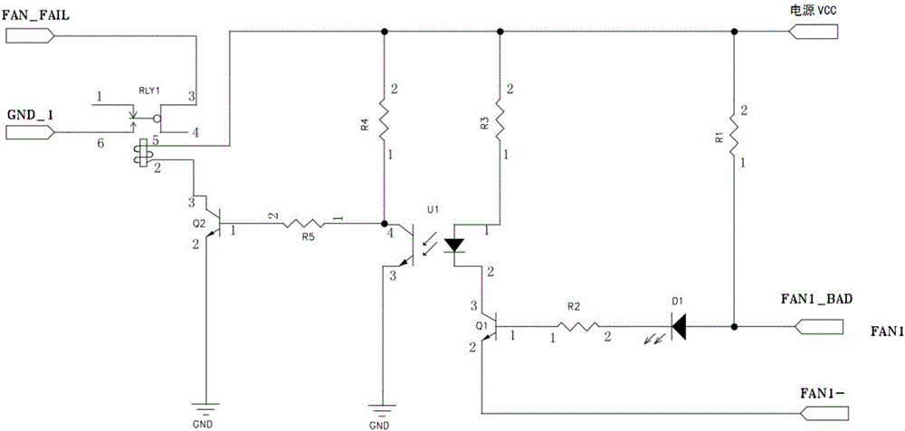
[0028] Such as figure 1 As shown, the present invention includes a signal conversion circuit, an isolation circuit and an alarm circuit for detecting the fan FAN1; wherein, the signal conversion circuit includes a relay RLY1, the pin 3 of the relay RLY1 is connected to a fault signal FAN_FAIL, and the pin 6 of the relay RLY1 is connected to a Fault signal ground GND1, one end of the wire package of the relay RLY1 is connected to the power supply VCC, and the other end is connected to the collector of the triode Q2, the emitter of the triode Q2 is grounded and its base is connected to the isolation circuit through the resistor R5, and the isolation circuit includes an optocoupler U1 and the triode Q1, wherein, the secondary pin 4 of the optocoupler U1 is respectively connected to the base of the triode Q2 and the power supply VCC, and a resistor R4 is set between the secondary pin 4 of the optocoupler U1 and the power supply VCC, and its secondary tube Pin 3 is grounded, the pr...
Embodiment 2
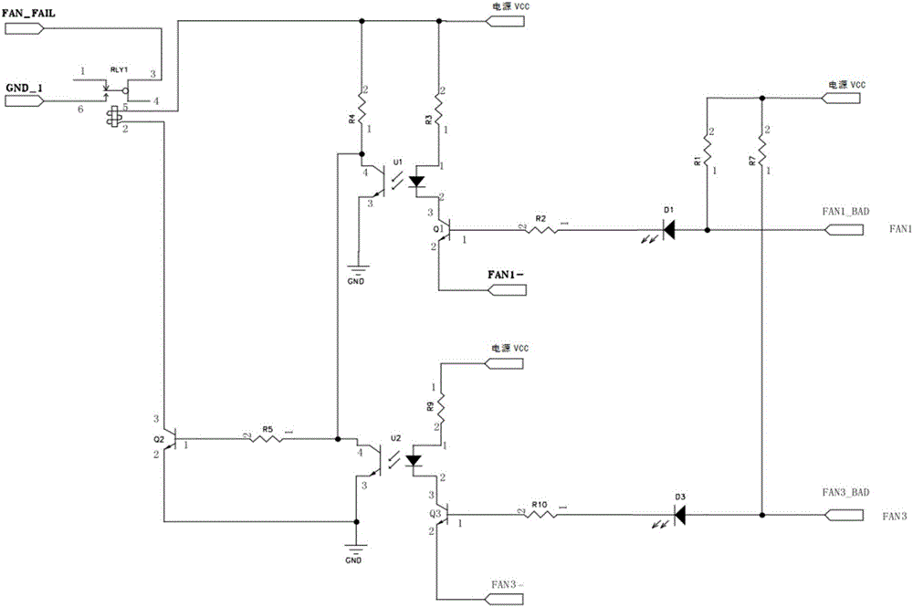
[0036] refer to figure 2 , on the basis of Embodiment 1, this embodiment adds an isolation circuit and an alarm circuit for detecting the fan FAN3. The newly added isolation circuit includes an optocoupler U2 and a transistor Q3, and the secondary pin 4 of the optocoupler U2 is connected to U1 Secondary side pin 4, its secondary side pin 3 is grounded, its primary side pin 1 is connected to the power supply VCC through resistor R9, primary side pin 2 is connected to the collector of triode Q3, and the emitter of triode Q3 is connected to fan ground FAN3 - connection, the base is connected to the alarm circuit through the resistor R10, and the alarm circuit includes a light-emitting diode D3 and a fan alarm signal FAN3_BAD, wherein the cathode of the light-emitting diode D3 is connected to the base of the triode Q3, and the anode of the light-emitting diode D3 is respectively connected to the power supply VCC is connected to the fan alarm signal FAN3_BAD, and a current-limitin...
Embodiment 3
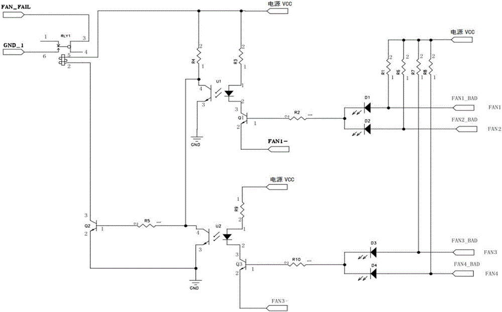
[0039] refer to image 3 , on the basis of Embodiment 2, this embodiment adds two new alarm circuits, which are the second alarm circuit used to detect the fan FAN2 and the fourth alarm circuit used to detect the fan FAN4, wherein the fan FAN2 and the fan FAN1 Common fan ground FAN1-, fan FAN3 and fan FAN4 common fan ground FAN3-, that is, several fans connected to the same isolation circuit for fault detection adopt a common fan ground setting;
[0040] The second alarm circuit includes a light-emitting diode D2 and a fan alarm signal FAN2_BAD, and the fourth alarm circuit includes a light-emitting diode D4 and a fan alarm signal FAN4_BAD, wherein the cathode of the light-emitting diode D2 is connected to the base of the transistor Q1 through a resistor R2, and the anode is connected to the power supply VCC respectively. It is connected to the fan alarm signal FAN2_BAD, and a current-limiting resistor R6 is set between the light-emitting diode D2 and the power supply VCC, tha...
PUM
 Abstract
Description
Claims
Application Information
 - R&D
- Intellectual Property
- Life Sciences
- Materials
- Tech Scout
- Unparalleled Data Quality
- Higher Quality Content
- 60% Fewer Hallucinations
Browse by: Latest US Patents, China's latest patents, Technical Efficacy Thesaurus, Application Domain, Technology Topic, Popular Technical Reports.
© 2025 PatSnap. All rights reserved.Legal|Privacy policy|Modern Slavery Act Transparency Statement|Sitemap|About US| Contact US: help@patsnap.com