Optical glass material homogeneity detection method and device

A technology of optical glass and uniformity, applied in measurement devices, optical instrument testing, testing optical performance and other directions, can solve problems such as increased test errors, discontinuous splicing marks, inability to high-precision defocusing and astigmatism, etc., to eliminate The effect of detecting errors and avoiding splicing marks

Active Publication Date: 2016-12-21
CHANGCHUN INST OF OPTICS FINE MECHANICS & PHYSICS CHINESE ACAD OF SCI
View PDF5 Cites 5 Cited by
  • Summary
  • Abstract
  • Description
  • Claims
  • Application Information

AI Technical Summary

Problems solved by technology

For the detection of the uniformity of large-aperture optical glass materials, it is too expensive to directly use large-aperture interferometers to solve the above problems. The existing technology cannot even manufacture interferometers and optical etalons that meet the requirements of caliber and test accuracy. Therefore, small-aperture based Interferometer combined with sub-aperture splicing technology to solve the problem of uniformity detection of large-aperture optical glass materials
However, the above solutions cannot test the defocus and astigmatism in the uniformity of materials with high precision, and because the tilt attitude of the inspected mirror is prone to change when the mirror is moved, the stitching process leaves discontinuous stitching in the final uniformity test results traces, resulting in increased uniformity test error

Method used


Image

  • Optical glass material homogeneity detection method and device
  • Optical glass material homogeneity detection method and device
  • Optical glass material homogeneity detection method and device

Examples


Embodiment Construction

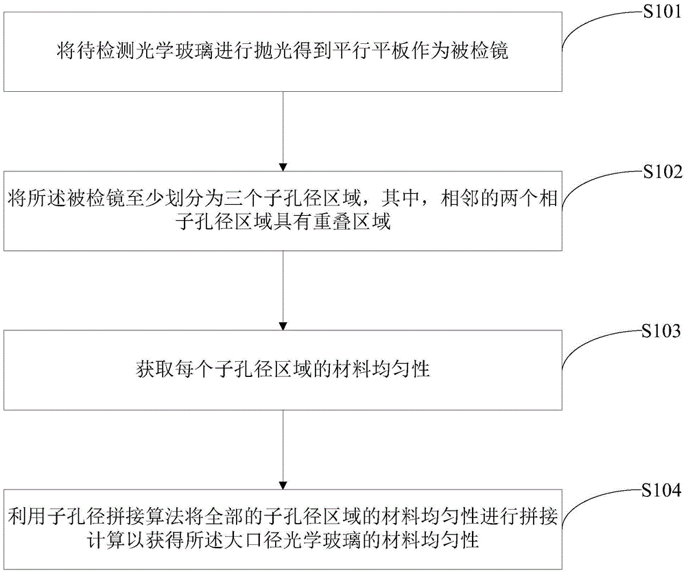
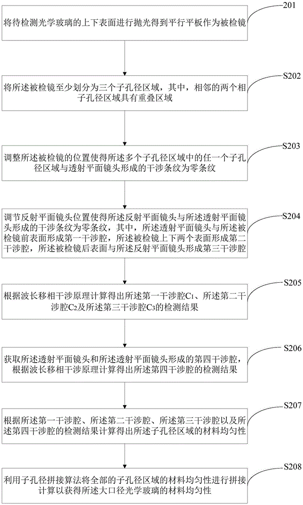
[0038] In order to enable those skilled in the art to better understand the solutions of the present invention, the following will clearly and completely describe the technical solutions in the embodiments of the present invention in conjunction with the drawings in the embodiments of the present invention. Obviously, the described embodiments are only It is an embodiment of a part of the present invention, but not all embodiments. Based on the embodiments of the present invention, all other embodiments obtained by persons of ordinary skill in the art without making creative efforts shall fall within the protection scope of the present invention.

[0039] The terms "first", "second", "third" and "fourth" in the description and claims of the present invention and the above drawings are used to distinguish similar objects, but not necessarily to describe a specific order or sequentially. It is to be understood that the terms so used are interchangeable under appropriate circums...


PUM


Abstract

The invention puts forward an optical glass material homogeneity detection method. A detected lens is divided into at least three sub-aperture areas, the material homogeneity of each sub-aperture area is calculated, and then, the material homogeneity of the detected lens is calculated using a sub-aperture stitching algorithm. In addition, the tilt posture of the detected lens is monitored and collected by a monitoring interferometer and a lateral plane mirror, and therefore, the homogeneity test results of different sub-apertures are completely consistent in tilt state. The amount of 'tilt' introduced to the sub-aperture interference detection result by de-focusing and astigmatism in homogeneity can be truly retained, so that splicing trace discontinuity in full-aperture homogeneity of the detected lens is avoided. According to the method put forward by the invention, in the process of large-aperture optical glass material homogeneity detection using a small-aperture phase-shifting interferometer, absolute detection of all wave aberrations of material homogeneity can be realized, and detection error caused by splicing trace discontinuity can be eliminated.

Description

technical field [0001] The invention relates to the technical field of optical interference measurement, in particular to a method and device for detecting material uniformity of optical glass. Background technique [0002] High-precision optical imaging lenses are usually composed of multiple optical lenses. In order to achieve ideal imaging quality, the transmitted wavefront of the optical lens is required to reach the diffraction limit, and the material uniformity of the optical glass is one of the main sources of the transmission wavefront error of the optical lens. . In addition, when using the zero-position compensation mirror method to detect the aspheric mirror surface shape, in order to obtain high-precision aspheric surface shape detection results, it is necessary to correct various error sources of the zero-position compensation mirror, including the uniformity of the glass material of the compensation mirror. Effects of aspheric wavefronts. In the above applica...

Claims


Application Information

Patent Timeline
Patent Type & Authority Applications(China)
IPC IPC(8): G01M11/02
CPCG01M11/0271
Inventor 苗亮张文龙刘钰马冬梅金春水
Owner CHANGCHUN INST OF OPTICS FINE MECHANICS & PHYSICS CHINESE ACAD OF SCI
Why Eureka
Try Eureka