A Cognitive Blind Equalization Method for Radar Channel Amplitude and Phase Correction

A phase correction and blind equalization technology, applied in the field of digital array radar, which can solve the problems of complex data transmission links and complex system implementation.

Inactive Publication Date: 2018-08-14
HOHAI UNIV
View PDF5 Cites 1 Cited by
  • Summary
  • Abstract
  • Description
  • Claims
  • Application Information

AI Technical Summary

Problems solved by technology

This process requires a complex data transmission link, and the system implementation is complex

Method used


Image

  • A Cognitive Blind Equalization Method for Radar Channel Amplitude and Phase Correction
  • A Cognitive Blind Equalization Method for Radar Channel Amplitude and Phase Correction
  • A Cognitive Blind Equalization Method for Radar Channel Amplitude and Phase Correction

Examples


Embodiment 1

[0119] First define the following simulation model to generate the data required for channel constant modular blind equalization verification:

[0120] The input signal of the cognitive equalizer is represented by the following formula:

[0121]

[0122] In the formula: k is discrete time sampling, x i (k) is the i-th channel equalizer input data; p(k) is the calibration signal input, which is a random phase modulation signal; is the discrete channel response of the i-th channel, Q is the number of channel response coefficients, ξ i (k) is the Gaussian noise of the i-th channel, Indicates convolution;

[0123] In the simulation, the simulation conditions of the constant blind equalization algorithm are shown in Table 1:

[0124] Table 1

[0125]

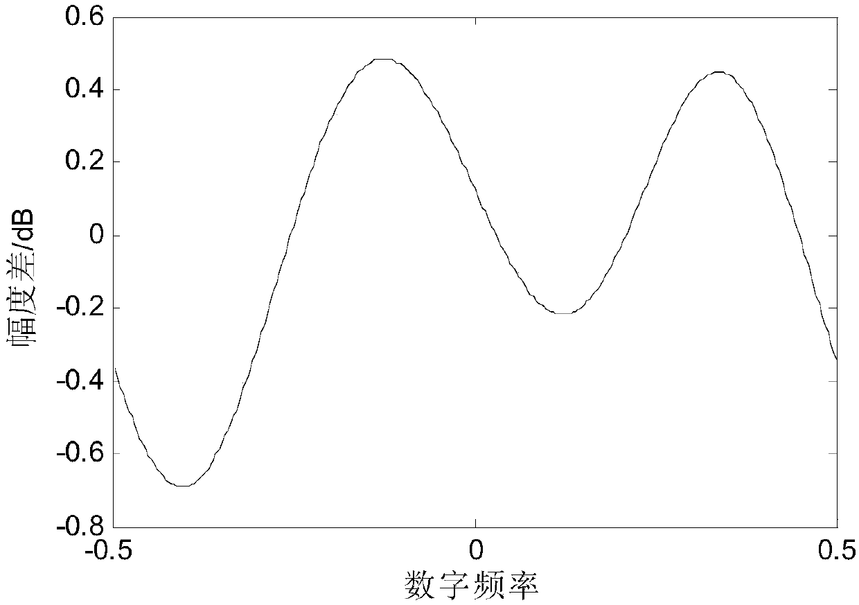
[0126] As shown in Figure 3(a)-(b), two channels with large gaps in amplitude and phase are used to verify the channel correction capability of the blind equalization method. The amplitude error between channels is 2dB (...

Embodiment 2

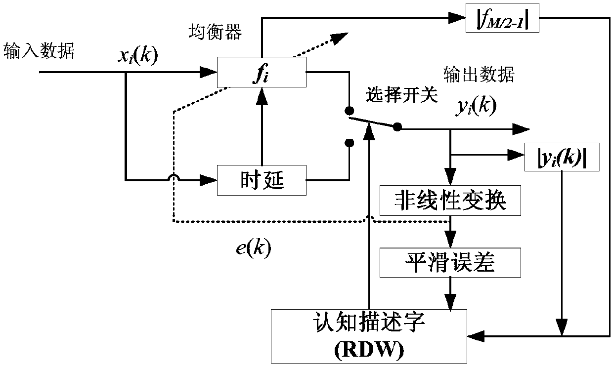
[0135] When there are errors such as bit errors in the input data, it will affect the convergence ability of the cognitive blind equalizer, thus making the equalizer unusable. In this embodiment, data with bit errors is used to verify the cognitive ability of blind equalization, and a bit error exists at the 4000th point of the data in simulation.

[0136] Figure 6(a)-(d) shows the change of parameters in cognitive descriptor RDW. It can be seen that the equalizer diverges at the position where the bit error occurs, so that the equalizer has not yet converged to a steady state at the sampling point at the end of the data. At this time, RDW=[0,1,0,1]. Therefore, this equalizer fails. The equalizer switches to pure delay mode. Otherwise, with the obtained equalizer equalization, more harsh channel characteristics will be obtained, such as Figure 7 As shown, compared with the situation before equalization in Fig. 3(a), the performance is worse.


PUM


Abstract

The invention discloses a cognitive blind equalization method for radar channel amplitude and phase correction. The method comprises: a calibration signal is sent to a blind equalizer; an output signal of the blind equalizer is transmitted to a selection switch; a plurality of related parameters of a convergence characteristic of the blind equalizer are monitored and a signal after equalization processing is outputted when the equalization process of the blind equalizer is normal; and when the equalization process of the blind equalizer is abnormal, equalization processing is not carried out and the signal is delayed and then is outputted. The blind equalizer employs several kinds of cognitive technologies for monitoring and whether the blind equalizer is normal is monitored by multiple parameters, thereby guaranteeing reliability of usage of the blind equalizer. According to the invention, closed-loop equalization of a digital array radar in a digital transmitting-receiving assembly is realized and data downloading and equalization coefficient returning are not required. Meanwhile, a cognitive method for a mean square error and weight coefficient vector monitoring is introduced, so that convergence reliability of the constant-modulus blind equalization method is improved and thus reliability of hundreds of radar channel equalizers of the digital array radar can be guaranteed.

Description

technical field [0001] The invention belongs to the field of digital array radar, in particular to a cognitive blind equalization method for radar channel amplitude and phase correction. Background technique [0002] There are inconsistencies in amplitude and phase in multiple channel bands of digital array radar. Even for narrowband systems, conventional channel calibration generally uses single-frequency signals to achieve consistency correction of a certain frequency. However, for other frequency points within a bandwidth of several megabytes, there are still differences in amplitude and phase. The traditional method uses adaptive equalization technology to realize the amplitude and phase correction of all frequency points in the band. However, adaptive equalization technology requires a reference channel. In the implementation process of digital array radar, the reference channel signal and each channel signal need to be transmitted below the array; after the adaptive ...

Claims


Application Information

Patent Timeline
Patent Type & Authority Patents(China)
IPC IPC(8): G01S7/02
CPCG01S7/02
Inventor 王峰蒋德富
Owner HOHAI UNIV
Why Eureka
Try Eureka