
DC-DC switching circuit based on variable resistor

A conversion circuit, DC-DC technology, applied in the direction of adjusting electrical variables, control/regulating systems, instruments, etc., can solve the problem of not being able to adjust the output voltage in real time, and achieve the effect of convenient operation

Inactive Publication Date: 2016-12-21
成都众乐泰科技有限公司
View PDF5 Cites 0 Cited by
  • Summary
  • Abstract
  • Description
  • Claims
  • Application Information

AI Technical Summary

Problems solved by technology

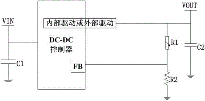
[0004] The purpose of the present invention is to provide a DC-DC conversion circuit based on a variable resistor to solve the problem that the output voltage cannot be adjusted in real time when the DC-DC conversion circuit realizes voltage conversion

Method used


Image

  • DC-DC switching circuit based on variable resistor
  • DC-DC switching circuit based on variable resistor

Examples


Embodiment 1

[0026] Such as figure 1 , figure 2 As shown, a variable resistor-based DC-DC conversion circuit of the present invention includes a power input terminal VIN and a DC-DC controller connected to the power input terminal, and the DC-DC controller includes an internal drive or an external drive, The internal drive or the external drive is connected to the output terminal VOUT of the power supply, the output terminal VOUT of the power supply is connected to a variable resistor R1, the variable resistor R1 is connected to the input port FB of the DC-DC controller, and the variable resistor R1 is connected to a drive device;

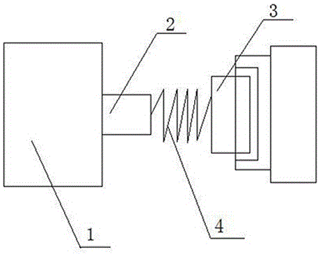
[0027] The driving device includes a motor, a rotating shaft connected to the motor at one end, and a sheet connected to the other end of the rotating shaft, the rotating shaft and the sheet are connected by a spring, and the sheet is installed in the groove of the variable resistor R1.

[0028] The power supply input terminal VIN inputs DC current to the DC...

Embodiment 2

[0030] Based on Embodiment 1, the motor is provided with three gears including first gear, second gear, and third gear. The first gear of the shaft rotates clockwise to 90°, the second gear clockwise to 180°, and the third gear to 270°. Each gear corresponds to a different resistance value

Embodiment 3

[0032] Based on the above embodiments, the spring is a torsion spring. After the motor is started, the rotating shaft is driven to rotate, and the rotating shaft rotates to make the spring generate torque so that the sheet rotates in the groove of the adjustable resistor, thereby changing the resistance value of the variable resistor R1.


PUM


Abstract

The invention discloses a DC-DC switching circuit based on a variable resistor. The DC-DC switching circuit comprises a power source input end VIN and a DC-DC controller connected with the power source input end; the DC-DC controller comprises an inner driver and an outer driver, and the inner driver and the outer driver are connected to a power source output end VOUT. The DC-DC switching circuit is characterized in that the power source output end VOUT is connected with the variable resistor R1, and the variable resistor R1 is connected with the input port FB of the DC-DC controller; the variable resistor R1 comprises a motor, a rotating shaft and a sheet, wherein one end of the rotating shaft is connected with the motor, the other end of the rotating shaft is connected with the sheet, the rotating shaft and the sheet are connected through a spring, and the sheet is installed in a groove of an adjustable resistor.

Description

technical field [0001] The invention relates to a direct current to direct current conversion circuit, in particular to a variable resistance-based DC-DC conversion circuit. Background technique [0002] At present, most electronic products are developing in the direction of lightness, thinness, low power consumption and environmental protection, and the voltage used by them is getting lower and lower. A DC-DC Converter Circuit is widely used in power supply circuits of electronic devices such as computers and liquid crystal displays, especially in DC regulated power supplies of related devices. [0003] At present, general electronic systems usually implement voltage conversion through DC-DC circuits. The principle is as follows: the output voltage is fed back to the controller through the voltage dividing resistor to realize the control of the output voltage value. However, when the voltage dividing resistor in the feedback circuit is fixed, the output The voltage is fixe...

Claims


Application Information

Patent Timeline
IPC IPC(8): G05F1/46
CPCG05F1/46
Inventor 周屹余凯何勇
Owner 成都众乐泰科技有限公司
Learn More