
Flywheel demonstration system and demonstration method thereof

A demonstration system and flywheel technology, which is applied in the flywheel demonstration system and its demonstration field, can solve the problems of large rotational inertia error and identification of celestial bodies, and achieve the effects of stable angle, stable control system and good controllability

Active Publication Date: 2016-12-21
NAT UNIV OF DEFENSE TECH
View PDF7 Cites 2 Cited by
  • Summary
  • Abstract
  • Description
  • Claims
  • Application Information

AI Technical Summary

Problems solved by technology

[0004] In the prior art, few mentions have been made about the demonstration system of the spacecraft flywheel. Chinese patent 201410291394.0 discloses a method for simulating the moment of inertia of a spacecraft by using a speed-up flywheel inertia simulator. The spacecraft simulation part is driven by a motor to rotate. However, the celestial body is not driven by a motor to rotate during the actual operation, and the method of simulating its moment of inertia does not identify the frictional resistance moment in the system, but needs to ignore the frictional damping and the moment of inertia of the speed reducer, and calculate it The moment of inertia is an equivalent value obtained from its flywheel, and the calculated moment of inertia of celestial bodies will have a large error

Method used


Image

  • Flywheel demonstration system and demonstration method thereof
  • Flywheel demonstration system and demonstration method thereof
  • Flywheel demonstration system and demonstration method thereof

Examples


Embodiment Construction

[0037] The embodiments of the present invention will be described in detail below with reference to the accompanying drawings, but the present invention can be implemented in various ways defined and covered by the claims.

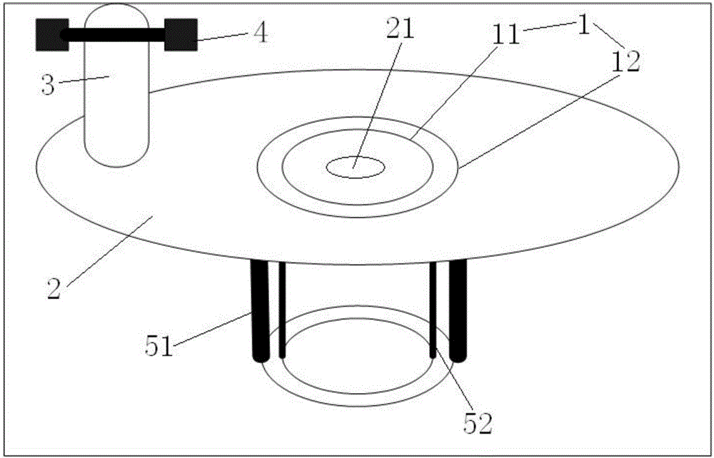
[0038] see figure 1A flywheel demonstration system, comprising a bearing (1) whose axis line is arranged vertically and a turntable (2) used to simulate the horizontal arrangement of the spacecraft, the lower end of the inner ring (11) of the bearing (1) and the demonstration platform fixed together, the turntable (2) is provided with a center hole, and the upper end of the outer ring (12) of the bearing (1) snaps into the center hole of the turntable (2) so that the turntable (2) can follow the outer ring of the bearing (1) around the bearing ( The inner ring of 1) rotates, and the drive motor (3) located on the radial periphery of the bearing is fixed on the turntable (2). The axis of the drive motor (3) is parallel to the axis of the bearing (1), and th...


PUM


Abstract

Provided is a flywheel demonstration system. The flywheel demonstration system comprises a bearing and a horizontally arranged rotary disc (2). The axis of the bearing is arranged in the vertical direction and the rotary disc is used for simulating a spacecraft and capable of rotating in a horizontal panel. A driving motor (3) is fixed on the rotary disc and connected with quality blocks (4) used for simulating flywheels of the spacecraft, and with a speed sensor used for detecting rotation speed of rotation shaft. An outer ring or an inner ring of the bearing (1) is connected with an angular displacement sensor used for detecting actual rotation angles of the rotary disc. The demonstration system fully simulates a space environment of a spacecraft. In a demonstration method, by identifying frictional resistance torque between the inner ring and the outer ring of the bearing and inputting the identified frictional resistance torque into a control system module, an accurate module is provided for the design of a control system; the control system is more stable; and the angle of the rotary disc is more stable.

Description

technical field [0001] The invention relates to a spacecraft demonstration system, in particular to a flywheel demonstration system and a demonstration method thereof. Background technique [0002] Flywheel system is an active control system widely used in spacecraft (star). The reaction torque caused by the continuous acceleration or deceleration of the flywheel acts on the stator of the driving motor fixed with the spacecraft, so that the spacecraft attitude changes to a stable state. The working principle of the flywheel system is the momentum moment theorem, namely The time derivative of the total momentum moment of the star (the sum of the momentum moment vectors of each component) is equal to the sum of the external moments acting on the star, especially when the sum of the external moment vectors is zero, the moment of momentum of the star is conserved. [0003] How to intuitively and realistically simulate the process of controlling the attitude of the spacecraft th...

Claims


Application Information

Patent Timeline
Patent Type & Authority Applications(China)
IPC IPC(8): G09B25/02
CPCG09B25/02
Inventor 汤国建郑伟刘鲁华张洪波邹东升
Owner NAT UNIV OF DEFENSE TECH
Learn More