
A New Control Method of Static Switch

A technology of static switch and control method, which is applied in the direction of emergency power supply arrangements, electrical components, circuit devices, etc., and can solve the problems of reducing the service life of devices, heating of thyristor gates, and inability to switch in time

Active Publication Date: 2019-04-05
青岛艾迪森科技股份有限公司
View PDF9 Cites 0 Cited by
  • Summary
  • Abstract
  • Description
  • Claims
  • Application Information

AI Technical Summary

Problems solved by technology

[0005] The purpose of the present invention is to overcome the above-mentioned defects in the existing voltage effective value comparison method and the trigger method of 360° full-cycle coverage, and propose a new type of static switch control method, which solves the problem that the AC input power cannot be switched in time when the AC input power is asynchronous. The problem of intermittent power supply when switching; solves the problem that when the AC input power is asynchronous, two sinusoidal half waves of the same polarity are generated during switching, and the problem of burning out transformers and motor loads; solves the problem when the AC input power is asynchronous , because the phases of the current and voltage are different, causing the problem of intermittent power supply during switching; it solves the problem that the trigger circuit and pulse transformer require large power, the SCR gate heats up, and the problem of reducing the service life of the device

Method used


Image

  • A New Control Method of Static Switch

Examples


Embodiment Construction

[0026] The present invention will be further described below in conjunction with accompanying drawing.

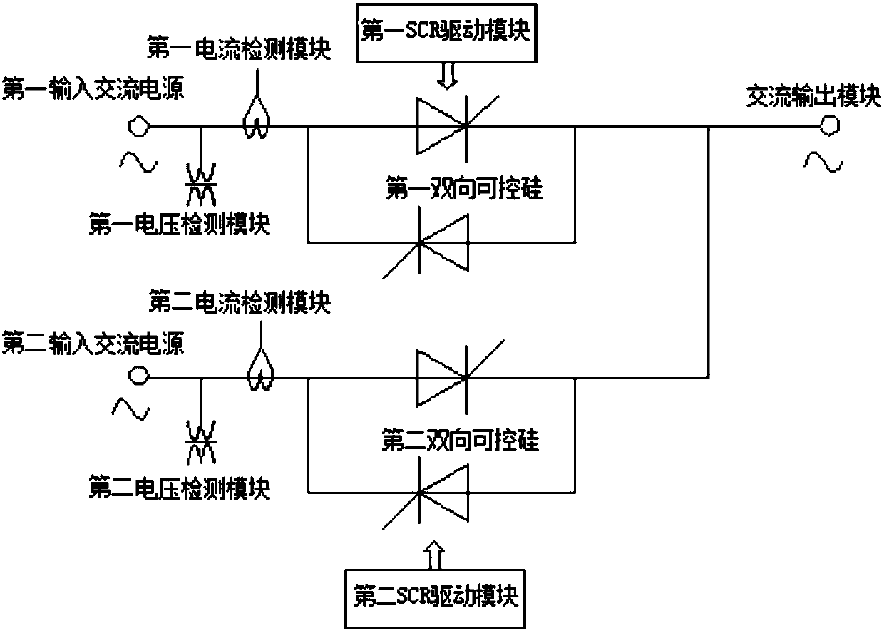
[0027] Such as figure 1 As shown, a novel static switch of the present invention includes a first input AC power supply, a first voltage detection module, a first current detection module, a first bidirectional thyristor and a first SCR driving module. Loop: a first voltage detection module for detecting voltage and a first current detection module for detecting current are arranged between the first input AC power supply and the first bidirectional thyristor, and the first bidirectional thyristor is connected to the first SCR drive module; It also includes a second loop composed of a second input AC power supply, a second voltage detection module, a second current detection module, a second bidirectional thyristor and a second SCR drive module, the second input AC power supply and the second bidirectional thyristor A second voltage detection module for detecting voltage a...


PUM


Abstract

The invention relates to a novel static switch and a control method thereof, which belong to the technical field of electronic switches and solve the problems of power supply interruption, high trigger power and the like in the prior art. According to the novel static switch and the control method thereof, a detection method is improved on the basis of an AC static switching technology, and the original method based on voltage detection is changed into a method based on voltage and current detection; and since a first voltage detection module for detecting voltage and a first current detection module for detecting current are arranged between a first input AC power supply and a first bidirectional silicon controlled rectifier, and a second voltage detection module for detecting voltage and a second current detection module for detecting current are arranged between a second input AC power supply and a second bidirectional silicon controlled rectifier, the problem of power supply interruption when the input power supplies are asynchronous is solved, the problem that a load is burnt by two sinusoidal half-waves with the same polarity when the input power supplies are asynchronous is solved, the problem of power supply interruption when the input power supplies have an inductive load or capacitive load is solved, and the problems that the power is high, gates of the silicon controlled rectifiers emit heat and the service life of the device is reduces are solved.

Description

technical field [0001] The invention relates to a control method of a novel static switch and belongs to the technical field of electronic switches. Background technique [0002] The static switch is used to switch the power supply between independent AC power sources with multiple circuits, and can provide fast switching to ensure uninterrupted power supply of sophisticated electronic equipment. The products involved include UPS power supply, STS system, etc. In the UPS power supply and STS system, the static switch currently used is a static switch composed of two sets of bidirectional thyristors or a static switch composed of two sets of AC contactors plus a set of bidirectional thyristors to realize the AC power supply of inverter output ( or main power) and alternate AC power. At present, the static switch in UPS power supply and STS system is controlled by voltage effective value comparison method, and the switching time is synchronous 4ms-5ms and asynchronous 8ms-10m...

Claims


Application Information

Patent Timeline
Patent Type & Authority Patents(China)
IPC IPC(8): H02J9/06
CPCH02J9/06H02J9/061H02J9/068
Inventor 王照忠
Owner 青岛艾迪森科技股份有限公司
Learn More