FPGA chaotic signal generator

A chaotic signal and generator technology, applied in the direction of secure communication through chaotic signals, secure communication devices, digital transmission systems, etc., can solve problems such as difficult programming, more time-consuming, and lack of versatility, and reduce computing time , the effect of saving hardware resources

Active Publication Date: 2016-12-21
GUANGDONG UNIV OF TECH
View PDF5 Cites 0 Cited by
  • Summary
  • Abstract
  • Description
  • Claims
  • Application Information

AI Technical Summary

Problems solved by technology

[0003] (1) The solution is only applicable to a specific chaotic system and is not universal, so it needs to be redesigned when replacing the system, and the development cycle i

Method used


Image

  • FPGA chaotic signal generator
  • FPGA chaotic signal generator
  • FPGA chaotic signal generator

Examples


Embodiment Construction

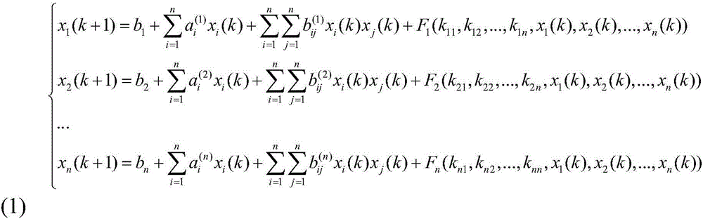
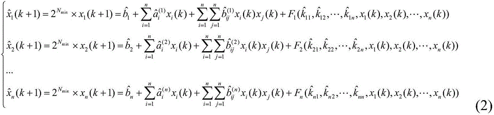
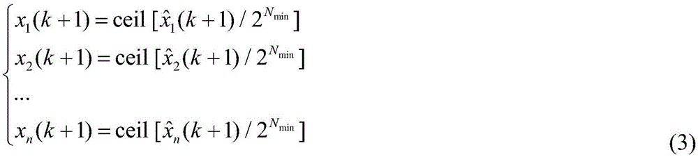
[0034] The embodiment of the present invention provides an FPGA chaotic signal generator that can be applied to different chaotic systems, and at the same time reduce the time required for calculation and reduce the consumption of hardware resources.

[0035] A kind of FPGA chaotic signal generator of the present invention comprises:

[0036] A chaotic system generation unit, a chaotic signal generation unit and a DA conversion unit;

[0037] The chaotic system generation unit is used to generate different chaotic systems by switching the switch, including: Lorenz system, Chen system, Lü system, 2 scroll Chua system, 4 scroll Chua system, grid 9 scroll Chua chaos system, 6-dimensional modular discrete system, 6-dimensional sinusoidal iterative discrete system;

[0038] The chaotic signal generating unit is used to generate the required chaotic signal in the chaotic system generated by the chaotic system generating unit;

[0039] The DA conversion unit is used to convert the ...


PUM


Abstract

The invention discloses an FPGA chaotic signal generator, and is applied to different chaotic systems, for the purpose of reducing time needed for operation and reducing consumption of hardware resources at the same time. The FPGA chaotic signal generator comprises a chaotic system generation unit, a chaotic signal generation unit and a DA conversion unit, wherein the chaotic system generation unit is used for generating different chaotic systems through switching of switches and comprises a Lorenz system, a Chen system, a Lv system, a two-scroll Chua system, a four-scroll Chua system, a grid nine-scroll Chua chaotic system, a six-dimensional modulus discrete system and a six-dimensional sine iteration discrete system; the chaotic signal generation unit is used for generating needed chaotic signals according to the chaotic systems generated by the chaotic system generation unit; and the DA conversion unit is used for converting the chaotic signals into forms which can be displayed in an oscilloscope.

Description

technical field [0001] The invention relates to the technical field of chaotic signal generation, in particular to an FPGA chaotic signal generator. Background technique [0002] The FPGA-based chaotic signal generation method currently reported is mainly aimed at the design of a specific chaotic system, and uses a floating-point arithmetic unit for calculation. The main shortcomings of this scheme are reflected in the following two aspects: [0003] (1) The solution is only applicable to a specific chaotic system and is not universal, so it needs to be redesigned when replacing the system, and the development cycle is long; [0004] (2) The design of the floating-point calculation module is difficult to program, and the calculation needs to consume more time and occupy more FPGA hardware resources. Contents of the invention [0005] The invention provides an FPGA chaotic signal generator which can be applied to different chaotic systems, and at the same time reduce the t...

Claims


Application Information

Patent Timeline
IPC IPC(8): H04L9/00
CPCH04L9/001
Inventor 温玉琼邱默禹思敏吕金虎
Owner GUANGDONG UNIV OF TECH
Why Eureka
Try Eureka