Methods of installing and implementing rigid pipes from vessels or floating supports

A technology of floating support and rigid pipe, which is applied in drilling pipe, casing, earthwork drilling and production, etc., and can solve problems such as inappropriate solutions

Active Publication Date: 2019-11-08
SAIPEM SPA
View PDF12 Cites 0 Cited by
  • Summary
  • Abstract
  • Description
  • Claims
  • Application Information

AI Technical Summary

Problems solved by technology

[0011] Such solutions applied to pipes as described above are not suitable if the top end of the rigid pipe needs to be wound out and in where it hangs over the sea

Method used


Image

  • Methods of installing and implementing rigid pipes from vessels or floating supports
  • Methods of installing and implementing rigid pipes from vessels or floating supports
  • Methods of installing and implementing rigid pipes from vessels or floating supports

Examples


Embodiment Construction

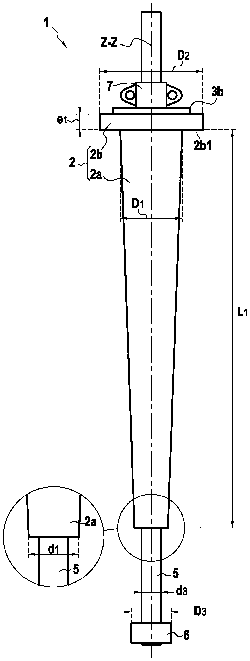
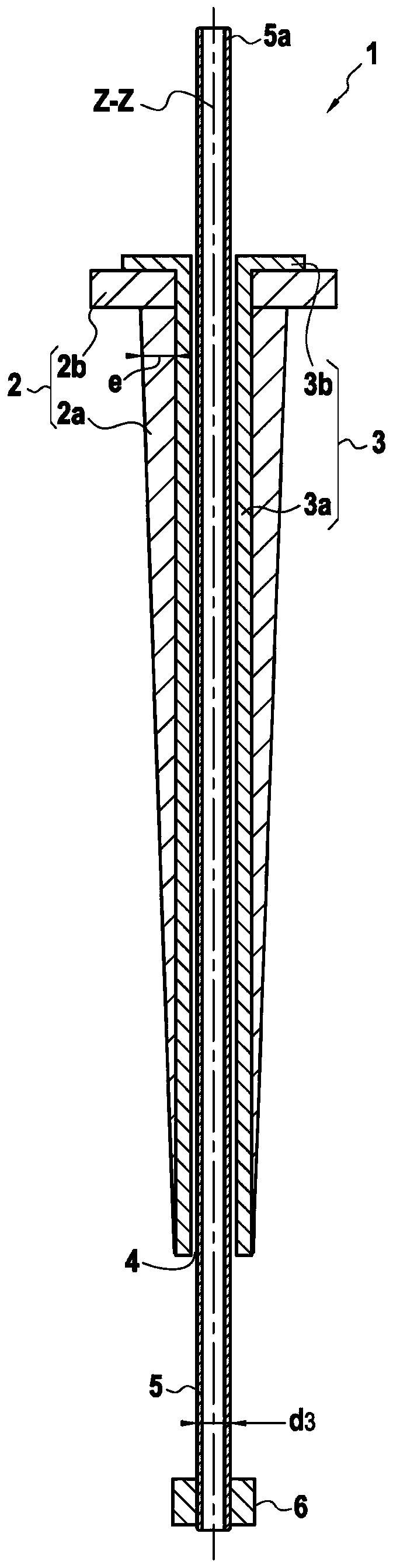
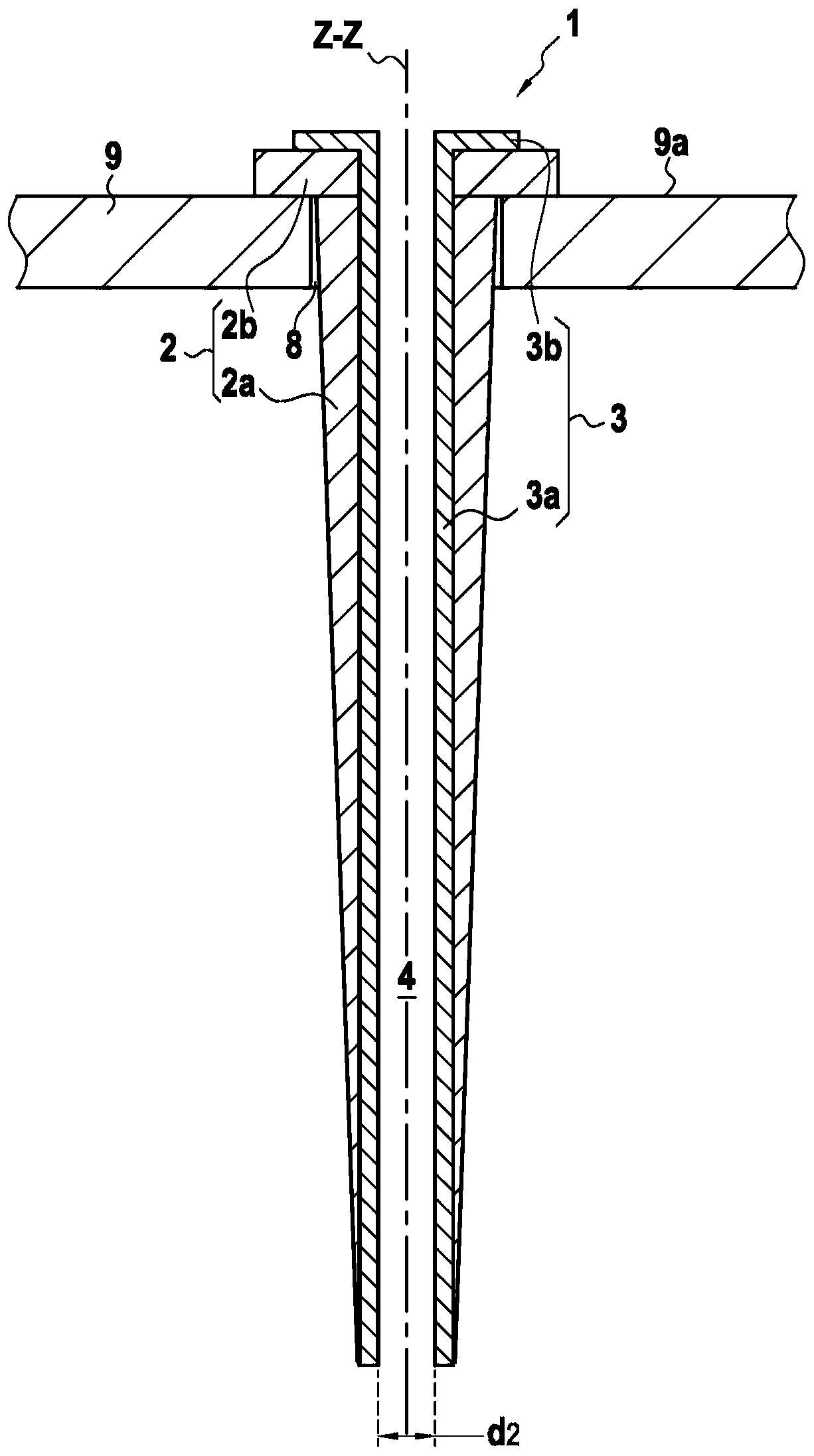
[0074] The sliding stiffener 1 shown in the attached drawings consists of a solid part made of a rigid solid material such as steel, possibly reinforced with glass fibers or synthetic fibers and consists of two parts: a conical main part 2a and a top fastening Plate 2b. The main part 2a of the bottom has an outer surface in the form of a frustoconical surface of revolution and extends a length L1. This main part is penetrated by said first cylindrical hole 4 having a circular axis on the same axis ZZ' as the axis of the frusto-conical outer surface and passing right through the main part. The diameter of the frustoconical outer surface of the main portion 2a varies between a maximum value D1 (at its top end) and a minimum value d1 (at its bottom end). In the figures, a conical part is shown with a rectilinear generator line (generator line) and a diameter that varies in a linear manner. In another embodiment, however, the generating line of the surface of revolution of the m...


PUM


Abstract

The invention relates to a method of installing and implementing a rigid pipe (10) called a main pipe, in which method the following steps are performed: a) removing one end of said main pipe from a vessel or floating support (13) on the sea surface lowering below sea level to connect the main pipe to submerged submerged equipment (16) in this position, preferably on the seabed (17); and b) subsequently keeping the main pipe submerged for a specified period of time, characterized by consists in passing said main pipe (10) into a cylindrical opening (4) of circular cross-section of a stress limiting device, said opening comprising a rigid support structure (9) firmly attached to said vessel or floating support device The inner lubricious coating (3), thereby enabling the main pipe to be in sliding contact with said lubricious coating during steps a) and b).

Description

technical field [0001] The invention relates to the field of subsea installation and implementation of rigid steel pipelines from floating supports or ships on the sea surface and lowering them into submerged water, preferably down to the seabed. Such rigid pipes may be referred to as "service" pipes implemented (for) testing or maintenance of said subsea equipment from the sea surface, or even for transferring production or service fluids to such equipment pipelines, especially subsea pipelines used to transport petroleum or related fluids, water sources or other parts of equipment. These rigid pipes are used in particular to test subsea equipment from the sea surface by delivering liquids or gases to the subsea equipment at different temperatures and pressures. In particular, the tests carried out consisted in cleaning the production subsea pipeline by filling it with a liquid, such as pressurized treated seawater, and cleaning it, for example by passing a scraper along the...

Claims


Application Information

Patent Timeline
Patent Type & Authority Patents(China)
IPC IPC(8): E21B19/09E21B19/22E21B17/01
CPCE21B17/017E21B19/09E21B19/22
Inventor 弗朗索瓦·R·皮奥内蒂尼古拉·沙佐弗朗索瓦·利落拉塞德里克·布吕吉耶
Owner SAIPEM SPA
Why Eureka
Try Eureka