Method and installation for laying a cylindrical pipe on a support

a cylindrical pipe and support technology, applied in the direction of sewer pipelines, shaft linings, tunnel linings, etc., can solve the problems of not allowing the use of steel pipes, high cost of pipes, and transportation problems of conventional assembly techniques

Inactive Publication Date: 2005-05-31
SERVICES PETROLIERS SCHLUMBERGER SA
View PDF14 Cites 39 Cited by
  • Summary
  • Abstract
  • Description
  • Claims
  • Application Information

AI Technical Summary

Benefits of technology

[0018]However, the invention may cover other applications, provided that the pipe can be laid freely from the top down.
[0035]It should be noted that, because the preform is made round pneumatically, this operation is particularly simple and inexpensive to implement, air being naturally available when required on the site; it is simply necessary to have a compressor generating a relatively low pressure, for example of the order of 1 bar (105 Pa).
[0042]the filamentary reinforcement comprises a braiding of crossed fibers, which is capable of preventing the radial expansion of the wall of the preform when it is made round;

Problems solved by technology

Pipes made of a composite are advantageously used when the corrosion problems are very considerable, and do not allow the use of steel pipes.
Such pipes are very expensive, in particular because of the need to machine the ends in order to join the pipe sections end to end.
Of course, this conventional assembly technique poses transportation problems.
In general, the pipes, are transported to the installation site by trucks, and the number of pipes transported is limited by their weight and their volume.
Furthermore, joining the pipes end to end is a lengthy, tedious and tricky task; for a length of 2,000 m, more than 150 joints would be required.
The process according to document FR-A-2 155 485 raises practical difficulties insofar as it is very difficult for the double-sphere expanding tool, which is provided inside the preform and allows it to be made round, to be properly held in place.
The process according to document EP-0 856 694 requires the use of a pressurized liquid, such as water, to make the preform round once it has been deposited in the trench; the process is tricky and relatively tedious to implement; in any case, it requires the liquid in question to be available on site.
In addition, with regard to a thermosetting resin, storing it at room temperature for a long period may initiate the crosslinking of the polymer.
This undesirable premature crosslinking may modify the behavior of the resin, or even prevent it from being used.
It is therefore necessary with the known devices to keep the preform, and the resin that it contains, in a container at a controlled temperature, including during transportation; this poses, of course, practical and cost problems.

Method used


Image

  • Method and installation for laying a cylindrical pipe on a support
  • Method and installation for laying a cylindrical pipe on a support
  • Method and installation for laying a cylindrical pipe on a support

Examples


Embodiment Construction

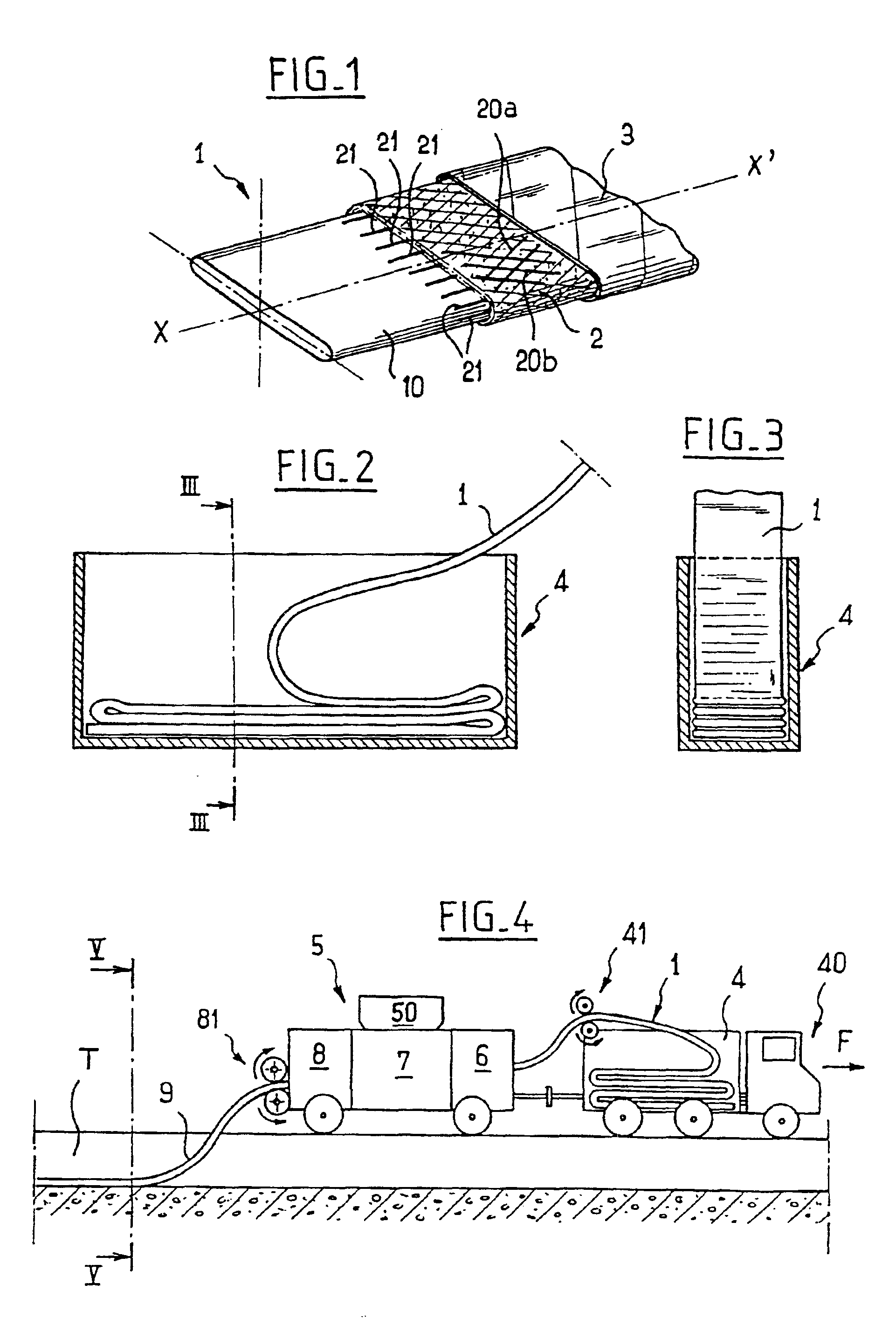
[0068]The initial preform 1, illustrated in FIG. 1, is folded over on itself, in this case flattened in the manner of a fire hose empty of water.

[0069]Its wall is flexible and deformable and comprises, from the inside outward, a thin tubular sealing skin 10, a filamentary reinforcement 2 and a protective sheath 3.

[0070]This preform 1, the longitudinal axis of which is denoted by X-X′, may be of relatively great length, for example about 1 000 to 2 000 m.

[0071]The inner skin 10 is, for example, made of synthetic rubber.

[0072]The filamentary reinforcement 2 consists of an assembly of fibers 20, such as glass or carbon fibers for example,' which will give the finished pipe the required mechanical and chemical properties.

[0073]The filamentary reinforcement 2 may advantageously consist of a number of concentric tubular structures inserted one into another, and each formed by a braiding of flat filaments or tapes 20, these being distributed in two series 20a, 20b which intersect symmetric...


PUM

PropertyMeasurementUnit
diameteraaaaaaaaaa
diameteraaaaaaaaaa
lengthaaaaaaaaaa

Abstract

A process and plant for laying a pipe in a trench comprising placing a flattened tubular preform in the trench, the perform having a reinforcement surrounding an inner seal, the reinforcement being impregnated with a resin, and inflating the perform in the trench.

Description

BACKGROUND OF THE INVENTION[0001]1. Field of the Invention[0002]The present invention relates to a process and a plant for laying a pipe in a trench.[0003]2. Description of Related Art[0004]Conventionally, pipes are made either of steel or of a composite composed especially of a filamentary tubular structure, for example based on glass fibers, which is impregnated with a curable resin, especially a resin which is curable under the effect of heat. The pipes are produced from elementary tube sections of predetermined length, for example 12 meters; by way of indication, their outside diameter is generally between 300 and 1 000 mm.[0005]Steel pipes are produced by butt welding a large number of sections; they are then covered with a corrosion-protection coating. When the fluids transported are highly corrosive, an internal coating must also be provided.[0006]Pipes made of a composite are advantageously used when the corrosion problems are very considerable, and do not allow the use of s...

Claims


Application Information

Patent Timeline
Patent Type & Authority Patents(United States)
IPC IPC(8): B29B15/10B29B15/12B29C63/00B29C69/02B29D23/00F16L1/028F16L1/038B29C35/00B29C35/02B29C49/00
CPCB29C63/0069B29C69/025F16L1/038B29D23/001D04C1/06B29C35/0272B29C49/00B29K2105/06B29L2023/006B29C2035/005D10B2403/0243
Inventor CORRE, PIERRE-YVESLEIGHTON, JAMESSALTEL, JEAN-LOUIS
Owner SERVICES PETROLIERS SCHLUMBERGER SA
Why Eureka
Try Eureka