Clutch control with hysteresis consideration

A friction clutch and hysteresis technology, applied in clutches, mechanical equipment, etc., can solve problems such as friction and elastic effect hysteresis, achieve precise transmission and improve driving comfort.

Active Publication Date: 2016-12-21
SCHAEFFLER TECH AG & CO KG
View PDF8 Cites 6 Cited by
  • Summary
  • Abstract
  • Description
  • Claims
  • Application Information

AI Technical Summary

Problems solved by technology

However, frictional and elastic effects in the region of the hydraulic lines can cause hysteresis effects, so that the actuation of the friction cl

Method used


Image

  • Clutch control with hysteresis consideration
  • Clutch control with hysteresis consideration
  • Clutch control with hysteresis consideration

Examples


Embodiment Construction

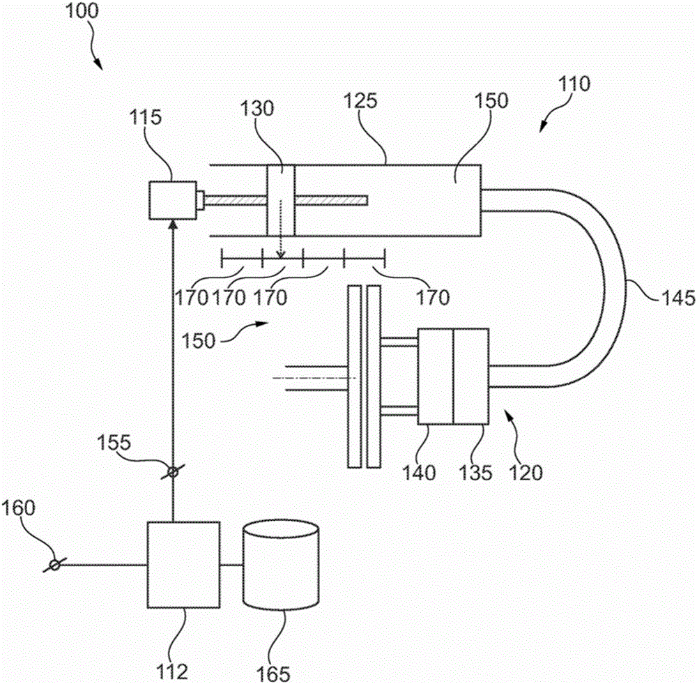
[0024] figure 1 A clutch system 100 is shown for use in a drive train, for example in a motor vehicle. The clutch system 100 includes a friction clutch 105 , an actuating device 110 and a control device 112 , which in the present embodiment are designed electrohydraulically. It is irrelevant for the consideration whether the torque transmittable via friction clutch 105 increases when the actuation by means of actuation device 110 is increased or decreased. Friction clutch 105 is especially capable of transmitting torque between the engine and the transmission. In one embodiment, friction clutch 105 is part of a dual clutch of a dual clutch transmission.

[0025] In the embodiment shown, the actuating device 110 can be controlled electrically. This is also a "clutch-by-wire" system if actuation is performed by means of an electro-sensitive clutch pedal. Actuating device 110 includes an electric actuator 115 and a hydrostatic line 120 . The hydrostatic line 120 includes a m...


PUM


Abstract

The invention relates to a friction clutch (105) which can be actuated by means of a slave piston (140) that is connected to a master piston (130) by means of a hydrostatic path (120). A method for controlling a torque which can be transmitted via the friction clutch (105) has the step of controlling the position of the master piston on the basis of a transmission function between positions of the master piston and the slave piston. The position of the master piston is additionally controlled on the basis of a hysteresis influence which is determined on the basis of a position of the master piston and a previous movement direction of one of the pistons. The hysteresis influence is determined on the basis of multiple support points, each of which is valid for a specified range of positions of the master piston.

Description

technical field [0001] The present invention relates to clutch control. In particular, the invention relates to controlling the hydraulic actuation of clutches, taking into account the hysteresis characteristic of the actuation. Background technique [0002] The drive train in a motor vehicle includes a friction clutch by means of which the transmission of torque in the drive train can be interrupted. Here, the friction clutch is actuated hydraulically. In the first embodiment, increased actuation causes the friction clutch to close, and in the second embodiment, causes the friction clutch to disengage. The elastic elements each provide a force counteracting the actuation. The hydraulic actuation comprises a master cylinder with a master piston and a slave cylinder with a slave piston, the two cylinders being hydraulically coupled to one another. If the position of the master piston is changed, this acts on the slave piston and correspondingly changes the torque transmit...

Claims


Application Information

Patent Timeline
IPC IPC(8): F16D48/06
CPCF16D48/066F16D2500/1026F16D2500/1045F16D2500/50287F16D2500/7041F16D2500/10412F16D2500/5012F16D2500/70235F16D2500/70668F16D2500/70684
Inventor 伊夫·贝尔廷·达斯-蒂约
Owner SCHAEFFLER TECH AG & CO KG
Why Eureka
Try Eureka