Energy-saving water supply system

A water supply system, energy-saving technology, applied in the field of ceramic filter water purifiers, can solve problems such as troublesome operation and filter loss.

Inactive Publication Date: 2017-01-04
佛山市永福金属材料有限公司
View PDF7 Cites 3 Cited by
  • Summary
  • Abstract
  • Description
  • Claims
  • Application Information

AI Technical Summary

Problems solved by technology

This operation is cumbersome and easy to cause loss to the filter element. Although the invention patent CN103157318A has improved the above defects, it still has the following defects. 1. Although the filter element does not need t

Method used


Image

  • Energy-saving water supply system
  • Energy-saving water supply system
  • Energy-saving water supply system

Examples


Embodiment 1

[0056] A detailed description will be given below of specific embodiments of the present invention according to the accompanying drawings.

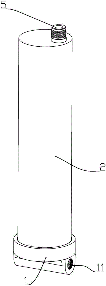
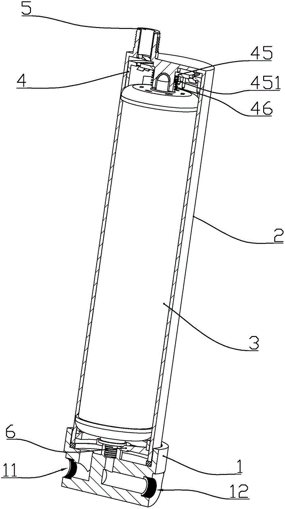
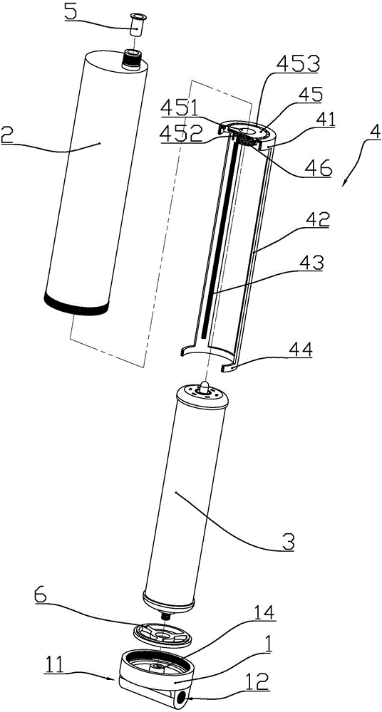
[0057] according to Figure 1-Figure 8 As shown, the energy-saving ceramic filter element water purifier with automatic cleaning function described in this embodiment includes a cylinder 2 and a cover 1 connected by threads, and is installed in the space between the cylinder 2 and the cover 1 The ceramic filter element assembly 3;

[0058] Both sides of the cover body are respectively formed with a non-drinkable water outlet interface 11 and a drinking water outlet interface 12; a drinking water outlet joint 14 is integrally formed in the middle of the inner bottom of the cover body, and the drinking water outlet joint 14 is connected to the drinking water outlet joint 14. The water outlet interface 12 is connected; the inner bottom of the cover is also formed with a non-drinking water outlet 111 connected with the non-drinking water out...

Embodiment 2

[0081] The difference between this embodiment and Embodiment 1 is that: the spring is sleeved on the drinking water outlet joint, and the two ends of the spring are abutted between the bottom surface of the cover body and the rotating connecting frame.

Embodiment 3

[0083] combine Figure 1 to Figure 9 As shown, the present embodiment is a kind of energy-saving water supply system, including the ceramic filter element water purifier P described in embodiment 1 or 2, and the running water pipe 8 connected with the water inlet joint on the ceramic filter element water purifier, through drinking The water pipe 82 is connected to the drinking water faucet M connected to the drinking water outlet 12 , and the non-drinking water faucet N is connected to the non-drinking water outlet 11 through the non-drinking water pipe 81 (providing washing water).

[0084] Said water pipe can be equipped with a master valve for controlling the whole water supply system near the ceramic filter element water purifier.

[0085] When the drinking water outlet faucet is open but not the drinking water outlet faucet is closed, due to the small flow rate of tap water at the drinking water outlet interface, the water flow through the blades of the water wheel per un...


PUM

PropertyMeasurementUnit
Angleaaaaaaaaaa
The inside diameter ofaaaaaaaaaa

Abstract

The invention discloses an energy-saving water supply system which comprises a ceramic filter element water purifier, a running water pipe connected with a water inlet joint on the ceramic filter element water purifier, a drinking water faucet connected with a drinking water outlet joint through a drinking water pipe, and a non-drinking water faucet connected with a non-drinking water outlet joint through a non-drinking water pipe, wherein a main valve used for controlling the whole water supply system can be mounted on the running water pipe close to the ceramic filter element water purifier; the ceramic filter element water purifier comprises a cylinder and a cover connected through threads, as well as a ceramic filter element assembly mounted in a space between the cylinder and the cover; a brush assembly is mounted in a position, which corresponds to the ceramic filter element, in the cylinder; the brush assembly is driven by water flow flowing through the interior of the ceramic filter element so as to achieve the function of automatically cleaning the ceramic filter element.

Description

[0001] This patent application is: [0002] The name is: A ceramic filter element water purifier [0003] The application number is: 2016102575125 [0004] The application date is: 2016.04.22 [0005] divisional application of the patent application. technical field [0006] The invention belongs to the field of water purification equipment, in particular to a water purifier with a ceramic filter element. Background technique [0007] At present, when the filter element of the ceramic filter element water purifier is cleaned, the water purifier is disassembled, and the dirt cleaned by scrapers or brushes on the ceramic filter element is washed away with clear water to restore the permeability. When the tap water pressure is low or the water quality is poor, it is necessary to remove the water purifier frequently to clean the ceramic filter element. This operation is cumbersome and easy to cause loss to the filter element. Although the invention patent CN103157318A has im...

Claims


Application Information

Patent Timeline
IPC IPC(8): B01D29/33B01D29/64B01D29/88
CPCB01D29/11B01D29/33B01D29/6415B01D29/88B01D2201/302B01D2201/40
Inventor 喻文武贾新奎
Owner 佛山市永福金属材料有限公司
Why Eureka
Try Eureka