3D free bending forming technology optimization method for complex metal components

A bending forming and process optimization technology, which is applied in the field of 3D free bending forming process optimization of metal complex components, achieves obvious economic benefits, high production efficiency, and simple and feasible methods

Active Publication Date: 2017-01-04
固航科技(常州)有限公司
View PDF5 Cites 20 Cited by
  • Summary
  • Abstract
  • Description
  • Claims
  • Application Information

AI Technical Summary

Problems solved by technology

[0005] The traditional bending technology of metal components has great limitations when bending pipes with complex axis shapes

Method used


Image

  • 3D free bending forming technology optimization method for complex metal components
  • 3D free bending forming technology optimization method for complex metal components
  • 3D free bending forming technology optimization method for complex metal components

Examples


Embodiment 1

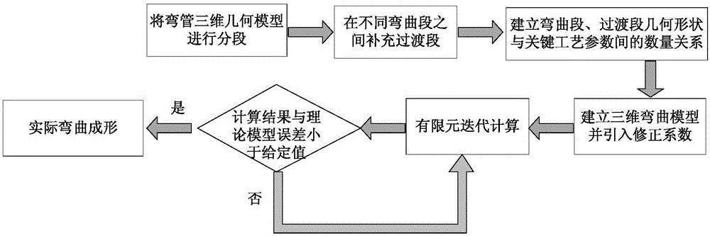
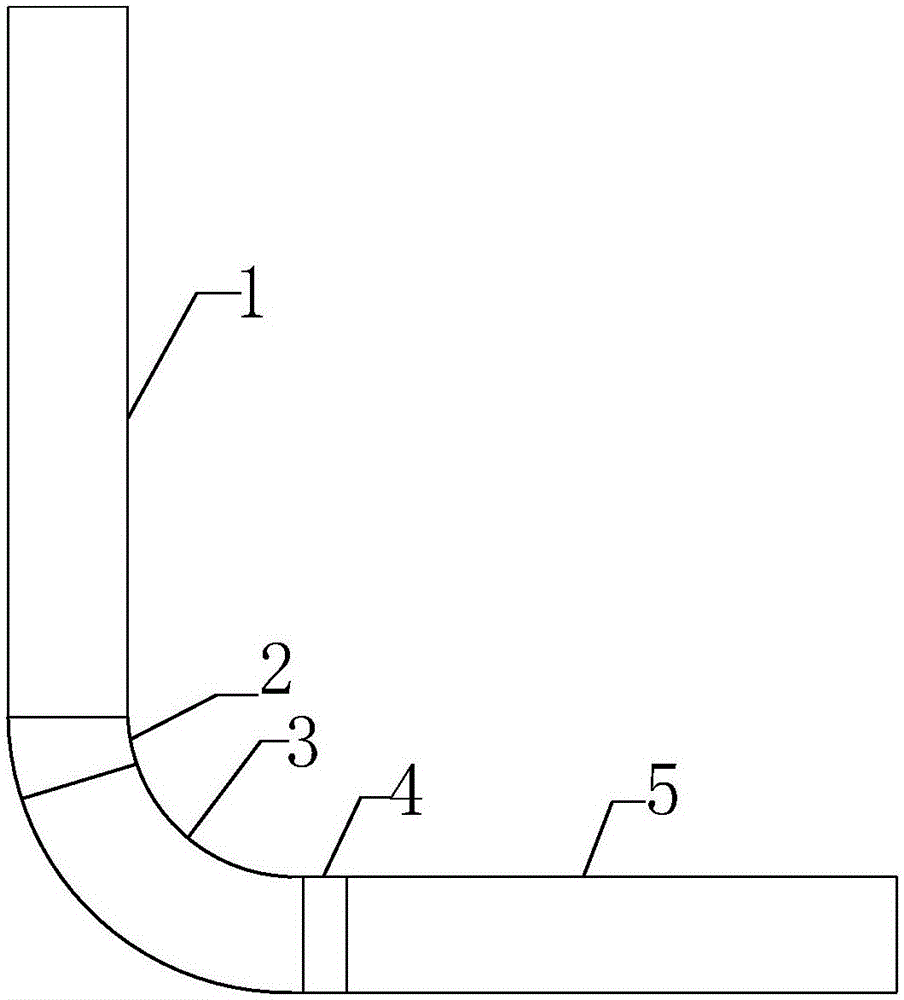
[0041] The first step is to divide the "L"-shaped elbow model with an outer diameter of 20mm, straight sections at both ends of 200mm, and a radius of 87.85mm into two straight sections and a curved (arc) section, such as image 3 As shown, they are respectively: the first straight section 1, the first curved section 3, and the second straight section 5;

[0042] In the second step, the first transition section 2 and the second transition section 4 are supplemented between the two straight sections and the curved sections;

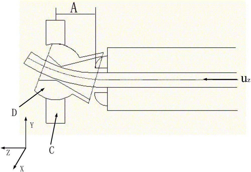
[0043] In the third step, the axial feeding speed of the pipe is v=10mm / s, and the distance between the center of the bending die and the front end of the guiding mechanism is A=30mm. Establish the quantitative relationship between the geometric parameters of the first straight section, the first transition section, the first curved section, and the second transition section, such as bending radius R, bending angle θ, etc., and the moving speed u and movin...

Embodiment 2

[0059] The first step is to divide the "U"-shaped elbow with an outer diameter of 15mm, straight sections at both ends and the bottom of 200mm, and a radius of 63.75mm into three straight sections and two curved sections; Figure 4 As shown, they are: the third straight section 6, the fourth straight section 10, the fifth straight section 14, the second curved section 8, and the third curved section 12;

[0060] The second step, such as Figure 4 As shown, the transition section is supplemented between the straight section and the curved section. Since the "U"-shaped elbow is a left-right symmetrical structure, there are four transition sections in the elbow: the third transition section 7, the fourth transition section Section 9, the fifth transition section 11, the sixth transition section 13, and the process parameters of the third transition section 7 and the fifth transition section 11, the fourth transition section 9 and the sixth transition section 13 are completely con...

Embodiment 3

[0085] The first step is to divide the "S"-shaped elbow with an outer diameter of 15mm and two semicircle radii of 100mm into two curved sections, such as Figure 5 As shown, they are respectively the fourth curved section 16 and the fifth curved section 19;

[0086] The second step is to add 4 transition sections on the two semicircles, which are respectively: the seventh transition section 15, the eighth transition section 17, the ninth transition section 18, and the tenth transition section 20; wherein the seventh transition section 15 and the The process parameters of the ninth transition section 18, the eighth transition section 17 and the tenth transition section 20 are completely consistent;

[0087] In the third step, the axial feeding speed of the pipe is v=10mm / s, and the distance between the center of the bending die and the guide mechanism is A=22.5mm. Establish the quantitative relationship between the geometric shape parameters of the transition section and the ...


PUM


Abstract

The invention discloses a 3D free bending forming technology optimization method for complex metal components. The method includes the steps that quantitative relations between geometrical shape parameters of a straight section, a transition section and a bent section and movement velocity u of a spherical bearing within the X / Y plane, pipe Z-axis feed-in velocity v, movement time t and a distance A between the center of a bending mold and the front end of a guiding mechanism are established; a finite element method is adopted for establishing a 3D bending model, and a correction factor k is introduced into the quantitative relations; the quantitative relations with the introduced correction factor k are adopted as bending technology parameters, bent pipe finite element repeated iterative computation is started, computation results are imported into geometry software to be processed, and the dimension difference between the computation results and the established 3D bending model is obtained through comparison; based on an established dimension error criterion, whether the correction factor k is modified, and iteration is performed again is determined; when the error is smaller than a set value, iteration is ended; final technology parameters are transmitted to equipment to execute actual bending forming.

Description

technical field [0001] The invention belongs to the technical field of advanced manufacturing of complex metal components, and in particular relates to a process optimization method for 3D free bending forming of complex metal components. Background technique [0002] Metal complex components with various cross-sectional shapes are widely used in many fields such as aerospace, nuclear power, automobiles, ships, petrochemicals, construction and other civil industries, and play an important role in reducing the production cost and weight of products. [0003] At present, the traditional metal component bending technologies mainly include press bending, stretch bending, winding bending, push bending and bending processes derived from the above basic processes. The above traditional pipe forming methods cannot meet the high-precision requirements of pipes when bending pipes with complex axis shapes. At the same time, according to the difference of the relative bending radius, t...

Claims


Application Information

Patent Timeline
Patent Type & Authority Applications(China)
IPC IPC(8): B21D11/02
CPCB21D11/02
Inventor 郭训忠马燕楠陶杰
Owner 固航科技(常州)有限公司
Why Eureka
Try Eureka