
Transition section optimization method based on three-dimensional free bending technology

A transition section and bending technology, applied in the field of transition section optimization based on three-dimensional free bending technology, can solve problems such as transition section errors

Inactive Publication Date: 2020-02-25
NANJING UNIV OF AERONAUTICS & ASTRONAUTICS +1
View PDF4 Cites 4 Cited by
  • Summary
  • Abstract
  • Description
  • Claims
  • Application Information

AI Technical Summary

Problems solved by technology

[0004] At present, the general three-dimensional free bending technology is mostly based on the uniform motion of spherical bearings. The bending member is decomposed into a straight section and a curved section, and the curved section is subdivided into a transition section and an arc section. However, the bending radius of the transition section under this method There is still a certain error with the target bending radius

Method used


Image

  • Transition section optimization method based on three-dimensional free bending technology
  • Transition section optimization method based on three-dimensional free bending technology
  • Transition section optimization method based on three-dimensional free bending technology

Examples


Embodiment 1

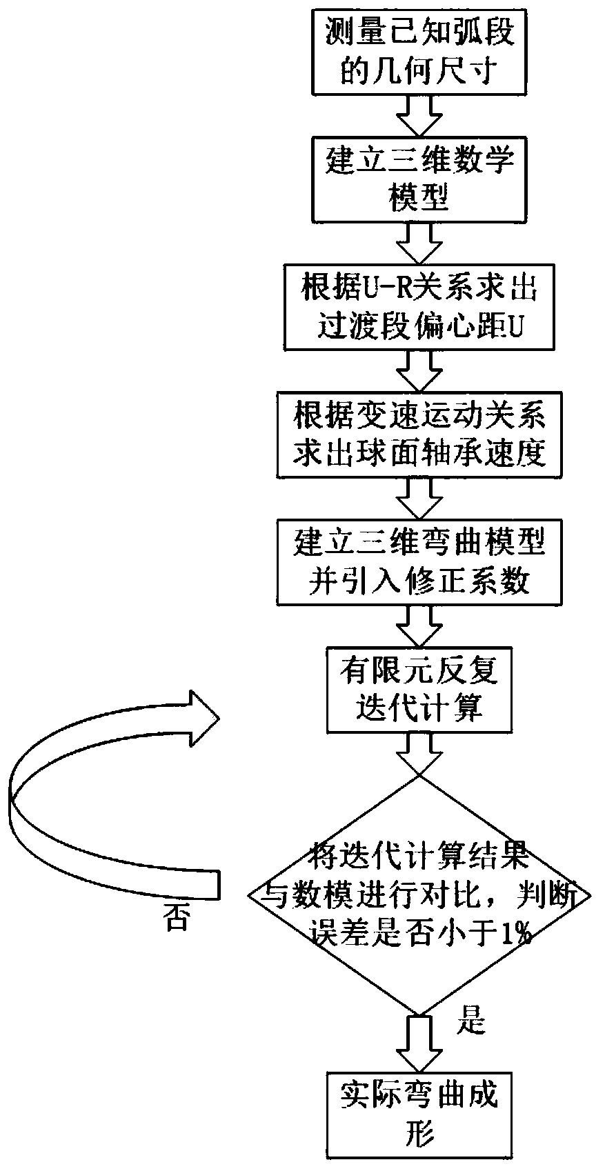
[0026] The first step is to establish a model and analyze the process of a curved pipe with an outer diameter of 15mm, a bending angle of 45°, and a bending radius of 90mm, and calculate the eccentricity U of the transition section according to the U-R relationship (the central axis of the guide mechanism and the bending die) The distance between the central axes is the eccentricity U):

[0027]

[0028] Movement speed of bending die spherical bearing

[0029] sport time

[0030]

[0031] In the second step, the finite element method is used to establish a three-dimensional bending model, and the correction coefficient k is introduced into the quantitative relationship described in the first step. The formula after the correction coefficient is introduced is as follows:

[0032] Movement speed of bending die spherical bearing

[0033] The third step is to use the quantitative relationship after introducing the correction coefficient k as described in the second s...

Embodiment 2

[0037] The first step is to establish a model and process analysis for a curved pipe fitting with an outer diameter of 15mm, a bending angle of 90°, and a bending radius of 90mm.

[0038] Movement speed of bending die spherical bearing

[0039] sport time

[0040]

[0041] In the second step, the finite element method is used to establish a three-dimensional bending model, and the correction coefficient k is introduced into the quantitative relationship described in the first step. The formula after the correction coefficient is introduced is as follows:

[0042] Movement speed of bending die spherical bearing

[0043] The third step is to use the quantitative relationship after introducing the correction coefficient k as described in the second step as the bending parameter, take the initial value of k as 1, start the repeated iterative calculation of the bent pipe finite element, import the calculation results into the geometric software CATIA for processing, and ...

Embodiment 3

[0047] In the first step, model building and process analysis are carried out for the curved pipe fittings with an outer diameter of 15mm, a bending angle of 180°, and a bending radius of 90mm.

[0048] Movement speed of bending die spherical bearing

[0049] sport time

[0050]

[0051] In the second step, the finite element method is used to establish a three-dimensional bending model, and the correction coefficient k is introduced into the quantitative relationship described in the first step. The formula after the correction coefficient is introduced is as follows:

[0052] Movement speed of bending die spherical bearing

[0053] The third step is to use the quantitative relationship after introducing the correction coefficient k as described in the second step as the bending parameter, take the initial value of k as 1, start the repeated iterative calculation of the bent pipe finite element, import the calculation results into the geometric software CATIA for pr...


PUM


Abstract

The invention discloses a transition section optimization method based on a three-dimensional free bending technology. Uniform motion of an original transition section bending die is optimized into variable motion; therefore, a corresponding bending die speed can be obtained at each time node, meanwhile, the optimized transition section bending die moves more stably, the ovality of the section ofthe bending component is reduced, in addition, the optimized bending die movement track is smoother, and the transition section and the bending section are basically tangent. The method specifically comprises the steps that the geometric dimension of a known arc section is measured, the eccentric distance U of a transition section is obtained according to the U-R relation, and then the bending diespeed corresponding to each time node is worked out through the variable-speed motion rule. meanwhile, a correction coefficient k is introduced, after each forming result is compared with the targetcomponent, if the error is not within the allowable range, correction parameters are adjusted to achieve iterative correction till the error reaches the allowable range, and it is regarded that the process is completed.

Description

technical field [0001] The invention belongs to the technical field of advanced manufacturing of metal complex components, in particular to a transition section optimization method based on three-dimensional free bending technology. Background technique [0002] At present, more and more three-dimensional complex bending components have been applied in aerospace, ships, construction, automobiles and other fields, and have played an important role in transporting materials, reducing weight, and reducing costs. [0003] Traditional bending processes include press bending, stretch bending, winding bending, push bending, etc. However, for some three-dimensional bending components with high precision requirements and complex shapes, the traditional process cannot meet the production needs. The emergence of three-dimensional free bending technology provides an effective way for the production of this type of parts. [0004] At present, the general three-dimensional free bending t...

Claims


Application Information

Patent Timeline
Patent Type & Authority Applications(China)
IPC IPC(8): G06F30/23G06F30/17G06F113/14
Inventor 郭训忠李光俊王巧玲李涛王辉
Owner NANJING UNIV OF AERONAUTICS & ASTRONAUTICS
Learn More