Punching machine

A punching machine and punching device technology, applied in the direction of punching tools, metal processing equipment, manufacturing tools, etc., can solve the problems of low punching position accuracy, inaccurate positioning of punching machines, etc.

Inactive Publication Date: 2017-01-04
TONGCHENG YUNCHENG PLATEMAKING
View PDF6 Cites 1 Cited by
  • Summary
  • Abstract
  • Description
  • Claims
  • Application Information

AI Technical Summary

Problems solved by technology

[0002] The punching machine is an active part that forces metal into the mold for sheet processing, stamping, molding, embos

Method used


Image

  • Punching machine
  • Punching machine

Examples


Embodiment Construction

[0015] The embodiments of the present invention will be described in detail below with reference to the accompanying drawings, but the present invention can be implemented in many different ways defined and covered by the claims.

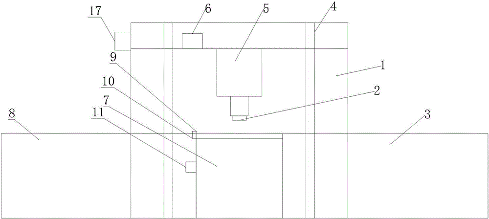
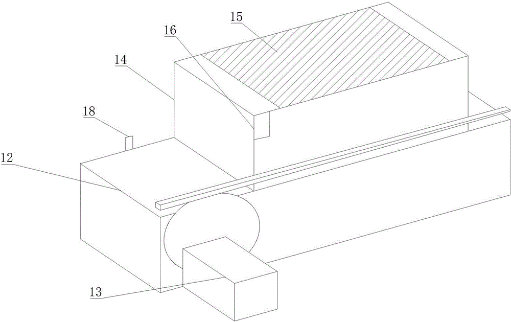
[0016] As shown in the drawings, a punching machine includes a punching device 1 and a conveying structure 3 located directly below the punching knife 2 of the punching device 1. The punching device 1 includes a frame 4, an Oil cylinder 5, punching knife 2 and oil cylinder control device 6 installed on the end face of the piston rod of oil cylinder 5, conveying structure 3 includes a workbench 7 directly below the punching knife 2, a conveying device 8 and a positioning device 9 on the workbench 7, The positioning device 9 includes a photoelectric sensor 10 and a positioning control device 11 positioned on the upper end surface of the workbench 7. The conveying device 8 transports the sheet material to the workbench 7. The conveying device 8 includes...


PUM


Abstract

The invention discloses a punching machine. The punching machine comprises a punching device and a conveying structure which is located under a punching knife of the punching device. The punching device comprises a rack, an oil cylinder, the punching knife and an oil cylinder control device, wherein the oil cylinder is arranged on the rack in an inverted manner, and the punching knife is mounted on the end face of a piston rod of the oil cylinder. The conveying structure comprises a workbench, a conveying device and a locating device, wherein the workbench is located under the punching knife, and the locating device is located on the workbench. The locating device comprises a first photoelectric sensor and a locating control device, wherein the first photoelectric sensor is located on the upper end face of the workbench. A panel is conveyed onto the workbench through the conveying device. According to the punching machine, a second photoelectric sensor detects the moving distance of a moving device, and precision of the moving distance of the moving device is enhanced; and rotating speed of a servo motor is constant, the first photoelectric sensor senses passing of the panel, and the position where the panel is stopped is accurate.

Description

technical field [0001] The invention belongs to the technical field of mechanical processing equipment, in particular to a punching machine. Background technique [0002] The punching machine is an active part that forces metal to enter the mold for sheet processing, stamping, molding, embossing, etc. The positioning of the existing punching machine is not accurate, and the accuracy of the punching position is not high. Contents of the invention [0003] The object of the present invention is to provide a punching machine with accurate punching positioning and high precision. [0004] The technical scheme adopted in order to solve the invention is: [0005] A punching machine, comprising a punching device and a conveying structure located directly below the punching knife of the punching device, the punching device includes a frame, an oil cylinder inverted on the frame, and a punching knife installed on the end face of the piston rod of the oil cylinder and the oil cyli...

Claims


Application Information

Patent Timeline
IPC IPC(8): B21D28/34B21D28/26B21D43/00
CPCB21D28/34B21D28/26B21D43/003
Inventor 张利明
Owner TONGCHENG YUNCHENG PLATEMAKING
Why Eureka
Try Eureka