Automatic shearing device for cold-rolled variable-thickness plates and shearing method based on automatic shearing device

A technology of variable thickness and automatic plate, applied in shearing machine equipment, shearing device, metal processing equipment and other directions, can solve the problem of not mentioning shearing realization method.

Active Publication Date: 2017-01-04
BAOSHAN IRON & STEEL CO LTD
View PDF8 Cites 18 Cited by
  • Summary
  • Abstract
  • Description
  • Claims
  • Application Information

AI Technical Summary

Problems solved by technology

[0006] Patent 201410828752.7 also mentions marking the strip at the exit of the roll gap and identifying the mark during shearing, but does not mention the implementation of shearing

Method used


Image

  • Automatic shearing device for cold-rolled variable-thickness plates and shearing method based on automatic shearing device
  • Automatic shearing device for cold-rolled variable-thickness plates and shearing method based on automatic shearing device
  • Automatic shearing device for cold-rolled variable-thickness plates and shearing method based on automatic shearing device

Examples


Embodiment 1

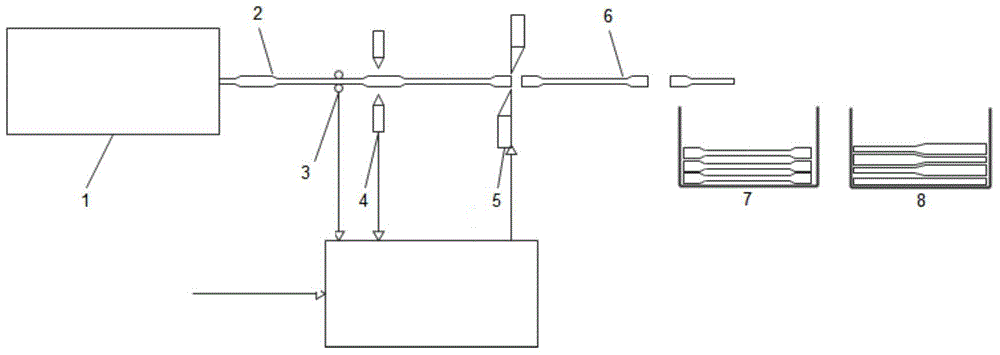
[0029] The structure of a device for automatic shearing of cold-rolled variable thickness plates provided by this embodiment is as follows Figure 4 As shown, it includes: a control device and a straightening device 1, a length measuring device 3, a thickness gauge 4, and a scissors 5 arranged in sequence. The length measuring device 3, the thickness gauge 4 and the scissors 5 are controlled by the control device.

[0030] The cutting method based on this embodiment is as follows: a thickness measuring device 4 is arranged in front of the scissors 5, and a length measuring device 3 is arranged in front of the thickness gauge. The control system recognizes that the thickness measuring device passes through the length tracking data and the actual thickness measurement value. The contour of the strip and determine the position of the strip at the scissors. At the beginning of the cutting, the cutting head is the lead that passes through the scissors. At this time, the size is often f...

Embodiment 2

[0032] The structure of a device for automatic shearing of cold-rolled variable thickness plates provided by this embodiment is as follows Figure 5 As shown, the difference from Embodiment 1 is that the equipment for automatic shearing of cold-rolled variable-thickness plates also includes a mark detector, which is arranged between the length measuring device and the thickness gauge, and is configured by Control device control.

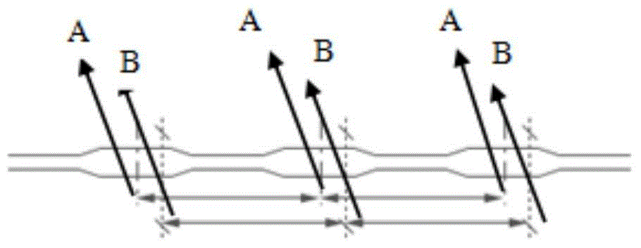
[0033] The difference between this method and method one is that the marks made on the strip 2 during rolling (such as Figure 7 Shown) to judge. Therefore, a thickness measuring device 4 is arranged in front of the scissors 5, a length measuring device 3 is arranged before the thickness measuring device, and a mark recognition device 9 is arranged after the length measuring device. At the beginning of the cutting process, the cutting head is passed through the scissors, and there is no cutting point mark on the strip 2. The control system will control ...


PUM


Abstract

The invention discloses an automatic shearing method for variable-thickness plates by means of an automatic shearing device for the cold-rolled variable-thickness plates. The automatic shearing method comprises the following steps that a thickness tester is arranged in front of a shear, a length tester is arranged in front of the thickness tester, and a control device recognizes the profiles of strips passing through the thickness tester and judges the positions of the strips at the shear according to length tracking data and measured thickness values, and compares the profiles with set profiles of the continuously-variable-thickness plates at the same time so as to determine the action time of the shear; and meanwhile, the control device further judges whether the profiles of sheared-off plates are qualified or not, so that whether the sheared-off plates are stacked into a finished product stack or a waste stack is determined. The automatic shearing method for the variable-thickness plates has the beneficial effect that the rolls of continuously-variable-thickness incoming materials can be efficiently and accurately sheared into the continuously-variable-thickness plates which can be directly used by users.

Description

Technical field [0001] The present invention is an automatic shearing method for cold-rolled variable-thickness plates, which can automatically shear rolls of variable-thickness incoming materials according to a set shape. Background technique [0002] In order to achieve the goal of reducing the weight of automobiles, the automotive industry is currently promoting the use of a strip with continuous changes in thickness obtained by rolling-thickened plates such as figure 1 Shown. The thickened plate can be rolled in a single sheet or in a coil. The coil rolling method is more efficient, but has positioning requirements for subsequent shearing. [0003] In order to facilitate rolling control, the set exit thickness profile is periodic. The cyclically changing strip thickness makes the subsequent shearing also have certain regularity. [0004] Existing cross-cutting units all have a fixed-length function, that is, the unit can cut out panels of the same length according to the data i...

Claims


Application Information

Patent Timeline
Patent Type & Authority Applications(China)
IPC IPC(8): B23D15/06B23D33/00B23Q17/20
CPCB23D15/06B23D36/005B21B2015/0014B23D15/08B23D33/02B23D33/12B23D36/00B21B2205/02B21B2261/043B21D35/006B21B15/0007B23D36/0008
Inventor 熊斐李山青姜正连
Owner BAOSHAN IRON & STEEL CO LTD
Why Eureka
Try Eureka