Pipe multi-head sawing machine

A technology for sawing machines and pipes, applied in metal sawing equipment, sawing machine devices, metal processing equipment and other directions, can solve the problems of low sawing efficiency, low efficiency and large volume.

Active Publication Date: 2017-01-04
SUZHOU KINKALTECK MACHINERY TECH
View PDF10 Cites 7 Cited by
  • Summary
  • Abstract
  • Description
  • Claims
  • Application Information

AI Technical Summary

Problems solved by technology

[0002] The sawing principle of the current multi-head sawing machine is the same as that of the single-head saw, which is to combine multiple sawing heads on one device, and use the clamping device to correspond to the sawing heads one by one. After the clamping device clamps the pipe, Then use the saw blade of the saw head to saw the pipe, but this multi-head sawing machine has the following disadvantages: 1. The sawing efficiency is low, and it needs feeding, feeding, and clamping action of the clamping device, and then the saw blade Feeding, retracting, loosening of the clamping device, and dis

Method used


Image

  • Pipe multi-head sawing machine
  • Pipe multi-head sawing machine
  • Pipe multi-head sawing machine

Examples


Embodiment Construction

[0030] The present invention will be described in further detail below through specific examples.

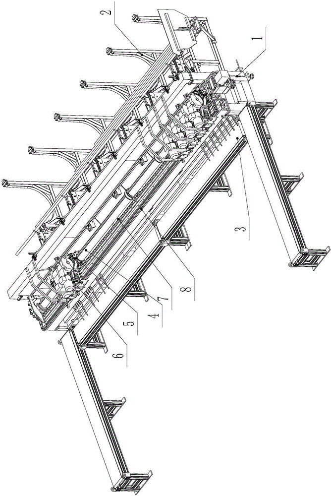
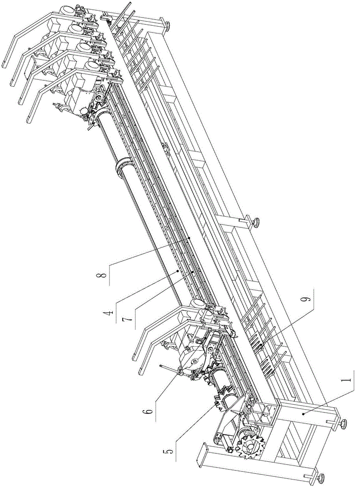
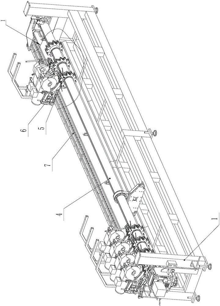
[0031] Such as Figure 1 to Figure 4 As shown, a multi-head sawing machine for pipes includes a frame 1 and a plurality of sawing heads 6 arranged on the frame 1, and a feed spindle 4 is rotatably installed on the frame 1, and the feed spindle 4 Driven by a rotary feed power device, the feed spindle 4 is provided with a transmission key 401, and the rotary feed power device is driven by a geared motor.

[0032] The feed spindle 4 is equipped with a material shifting gear set 5 corresponding to the number of sawing heads 6, and a circularly arranged material shifting tooth groove 503 is arranged on the material shifting gear set 5. On the material shifting gear set 5, A feed gap 504 is provided to facilitate the entry of the saw blade 604 of the sawing head 6, and the depth of the feed gap 504 is greater than the pipe diameter of the pipe;

[0033] Such as Figure 4 As shown, th...


PUM


Abstract

The invention discloses a pipe multi-head sawing machine. The pipe multi-head sawing machine comprises a rack and a plurality of sawing heads arranged on the rack. A feed spindle is rotationally mounted on the rack and driven by a rotary feed power device. Material poking gear sets are mounted on the feed spindle and each provided with circumferentially-formed material poking gears. Feed clearances are arranged on each material poking gear set, and the depth of the feed clearances is larger than the pipe diameter of a pipe. The sawing heads are arranged on the rack and located on the rotating downstream sides of the material poking gear sets. Saw blades of the sawing heads are located at the upper sawing stations of the material poking gear sets and correspond to the positions of the feed clearances, and the length of the parts, stretching into the feed clearances, of the saw blades is larger than the pipe diameter of the pipe. Automatic feeding devices used for transversely feeding the pipe into material poking gear grooves of the material poking gear sets are arranged on the rotating upstream sides of the material poking gear sets. According to the multi-head sawing machine, taking, feeding, sawing and discharging are completed within one rotating period through the rotary material poking gear sets, and the sawing efficiency is greatly improved.

Description

technical field [0001] The invention relates to a multi-head sawing machine for sawing pipes, in particular to a multi-heads sawing machine for sawing pipes during the feeding process of the pipes. Background technique [0002] The sawing principle of the current multi-head sawing machine is the same as that of the single-head saw, which is to combine multiple sawing heads on one device, and use the clamping device to correspond to the sawing heads one by one. After the clamping device clamps the pipe, Then use the saw blade of the saw head to saw the pipe, but this multi-head sawing machine has the following disadvantages: 1. The sawing efficiency is low, and it needs feeding, feeding, and clamping action of the clamping device, and then the saw blade Feeding, retracting, loosening of the clamping device, and discharge of the material, it takes a long time to saw a pipe and the efficiency is very low; 2. The cost of this sawing machine is high, because every Each step requ...

Claims


Application Information

Patent Timeline
IPC IPC(8): B23D45/10B23D47/04
Inventor 柯晓华
Owner SUZHOU KINKALTECK MACHINERY TECH
Why Eureka
Try Eureka