
Locating fixture for realizing coaxial assembling of two pipelines

A positioning tooling and coaxial technology, applied in the direction of metal processing, manufacturing tools, metal processing equipment, etc., can solve the problems of poor sealing performance and tensile strength, to prevent pipe displacement and deformation, product sealing performance and anti-corrosion Good tensile strength and easy installation

Active Publication Date: 2017-01-04
CHENGDU SHANHAI HEAT SHRINKABLE PROD
View PDF7 Cites 4 Cited by
  • Summary
  • Abstract
  • Description
  • Claims
  • Application Information

AI Technical Summary

Problems solved by technology

[0003] In order to overcome the defects of poor sealing performance and tensile strength of the connected product caused by the use of the existing hot-melt injection molding process to connect steel conduits and PE pipes, the present invention provides a positioning tool for coaxial assembly of two pipes. The positioning tool can realize the coaxial assembly of the steel conduit and the PE pipe. The steel conduit and the PE pipe can be connected together without hot-melt injection molding. The product after connection has good sealing performance and tensile strength, and also realizes two Coaxial assembly of the root pipe without eccentricity

Method used


Image

  • Locating fixture for realizing coaxial assembling of two pipelines
  • Locating fixture for realizing coaxial assembling of two pipelines
  • Locating fixture for realizing coaxial assembling of two pipelines

Examples


Embodiment 1

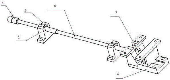
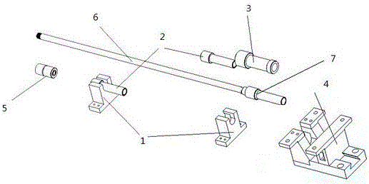
[0048] Such as figure 1 and figure 2 As shown, this embodiment provides a positioning tool for the coaxial assembly of two pipelines. The tooling includes a positioning frame 1, a positioning sleeve 2, a sleeve 3 and a positioning mold 4. The positioning sleeve 2 is assembled on the positioning frame 1. A positioning frame 1 is equipped with a positioning sleeve 2, and the sleeve 3 is assembled on the positioning mold 4. After assembly, the axes of the positioning sleeve 2 and the sleeve 3 are on the same straight line.

[0049] The positioning tool also includes a tailstock positioning sleeve 5 .

[0050] The tailstock positioning sleeve 5 is a stepped shaft, and the interior of the stepped shaft is hollow.

[0051] The positioning frame 1 is provided with a positioning sleeve groove 10 , and the positioning sleeve 2 is assembled in the positioning sleeve groove 10 .

[0052] Such as Figure 4 and Figure 5 As shown, the positioning sleeve 2 is a stepped shaft, and the ...

Embodiment 2

[0073] This embodiment is basically the same as Embodiment 1, except that the positioning sleeve and the positioning frame are fixedly connected together, and the positioning sleeve can be directly integrally formed with the positioning frame, or the positioning sleeve can be directly welded on the positioning frame. The sleeve and the fixing frame are fixedly connected together, and the sleeve can be directly integrally formed with the fixing frame, or can be directly welded on the fixing frame. As for the number of positioning sleeves and positioning frames, it is determined according to the length of the pipe, as long as the pipe can be well supported to prevent the pipe from bending and deforming during extrusion.


PUM


Abstract

The invention discloses a locating fixture for realizing coaxial assembling of two pipelines. The locating fixture comprises locating frames, locating sleeves, a bushing and a locating die, wherein the locating sleeves are assembled on the locating frames; each locating frame is provided with each locating sleeve; the bushing is assembled on the locating die; after the locating sleeves and the bushing are assembled, the axis of the locating sleeves and the axis of the bushing are located on the same straight line. By the action of the locating sleeves and the bushing, the locating fixture for coaxially assembling the two pipelines is realized; due to the locating action of the locating fixture, the two pipelines can be coaxially assembled without deviation; the assembling quality can meet the requirement; both the sealing property and the tensile strength of a steel guide pipe and a PE pipe which are assembled by the fixture can meet the use requirement on natural gas conveying.

Description

technical field [0001] The invention relates to a positioning tool, in particular to a positioning tool for realizing the coaxial assembly of two pipelines. Background technique [0002] When the natural gas is transported from the gas company to the user, the buried PE pipe is used for transportation between the user and the natural gas, and the steel conduit is used for transportation after leaving the ground. Therefore, PE pipes and steel conduits must be used at the same time for gas transportation. Due to the particularity of gas transportation, strict sealing is required to prevent gas leakage, so the requirements for the connection of transportation pipelines are very strict. As for the connection between the steel conduit and the PE pipe, the method currently used is the hot-melt injection molding process, so that the steel conduit and the PE pipe are connected together. This method is simple and suitable for mass production, but the hot-melt injection molding method...

Claims


Application Information

Patent Timeline
IPC IPC(8): B23P19/02B23P19/027
CPCB23P19/024B23P19/027
Inventor 郑军黄谋刚邓文松
Owner CHENGDU SHANHAI HEAT SHRINKABLE PROD
Learn More