Novel tool changing structure for tool magazine

A tool magazine, a new type of technology, applied in the direction of clamping, supporting, positioning devices, etc., can solve the problems of high failure rate of mechanical and electrical parts, difficult long-term guarantee of tool change accuracy, high production cost, etc., to achieve fast and safe tool replacement, reduce The effect of tool change misoperation and failure

Inactive Publication Date: 2017-01-04
SHENZHEN SXH PRECISION MACHINERY EQUIP
View PDF5 Cites 7 Cited by
  • Summary
  • Abstract
  • Description
  • Claims
  • Application Information

AI Technical Summary

Problems solved by technology

[0002] Existing machine tool tool magazine tool change mechanisms mainly include cam type and pneumatic type, the structure is relatively complex, the manufacturing cost is high, and the tool change accuracy is not easy to guarantee for a long time, and the tool change action needs to involve the electrical control part (deceleration motor, solenoid valve, etc. ), it needs to be combined with mechanical and electrical to realize the tool change action, and the tool change time needs at least 6.4 seconds; at the same time, high-level technical personnel are required to install and debug the tool magazine to realize the tool change action, and the cam type with geared motor tool change Arm, complex structure, high production cost, high failure rate of mechanical and electrical parts; and high cost, a complete set of tool changing device is at least tens of thousands of yuan

Method used


Image

  • Novel tool changing structure for tool magazine
  • Novel tool changing structure for tool magazine
  • Novel tool changing structure for tool magazine

Examples


Embodiment Construction

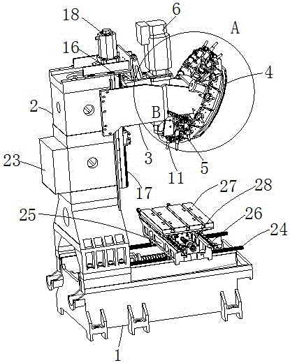
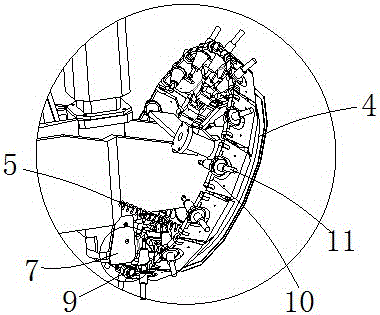
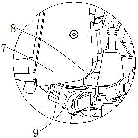
[0017] Such as Figure 1 to Figure 5 As shown, a new type of tool magazine tool change structure, including a base 1 and a host column 2 connected to the base 1, the host column 2 is connected to the tool magazine bracket 3, and the end of the tool magazine bracket 3 is movably connected to the tool magazine rotating seat 4, The tool magazine revolving seat 4 is connected with the tool magazine support 3 through the tension spring 5, and the main shaft 6 is arranged on one side of the host column 2, and the main shaft 6 is connected with the host column 2 through the lifting control mechanism, and the free end of the main shaft 6 is connected with the gripping plate 7 , Grab knife pressing plate 7 is provided with protruding arc surface 8, is provided with a plurality of equidistant notches on the knife storehouse rotating seat 4, is provided with knife storehouse roller 9 in the notch, and the arc shape of grasping knife press plate 7 The surface 8 corresponds to the peripher...


PUM


Abstract

The invention relates to a novel tool changing structure for a tool magazine. The novel tool changing structure for the tool magazine comprises a base and a host computer stand column connected with the base, wherein a tool magazine bracket is connected to the host computer stand column, a tool magazine rotating seat is movably connected to the end portion of the tool magazine bracket, and the tool magazine rotating seat is connected with the tool magazine bracket through an extension-retraction spring; a main shaft is arranged on one side of the host computer stand column, the main shaft is connected with the host computer stand column through a lifting control mechanism, and a tool catching clamp plate is connected to the free end of the main shaft; tool magazine rollers are arranged on the tool magazine rotating seat, and the arc face of the tool catching clamp plate is corresponding to the peripheral face of the tool magazine roller; a tool claw is arranged between every two adjacent tool magazine rollers, and a tool handle is clamped in the tool claw. According to the principle of tool exchange and the tool changing mechanism with the requirements for emphatically simplifying the tool magazine, the novel tool changing structure reduces wrong actions and faults of the tool exchange; the connection of the main shaft and the tool handle is solved by skillfully using the extension and retraction of the spring; the tool can be changed quickly and securely by means of up-down slide of the main shaft arranged on a host computer along the Z axis and a tool broaching mechanism in the interior of the main shaft.

Description

technical field [0001] The invention relates to a novel tool changing structure of a tool magazine. Background technique [0002] Existing machine tool tool magazine tool change mechanisms mainly include cam type and pneumatic type, the structure is relatively complex, the manufacturing cost is high, and the tool change accuracy is not easy to guarantee for a long time, and the tool change action needs to involve the electrical control part (deceleration motor, solenoid valve, etc. ), it needs to be combined with mechanical and electrical to realize the tool change action, and the tool change time needs at least 6.4 seconds; at the same time, high-level technical personnel are required to install and debug the tool magazine to realize the tool change action, and the cam type with geared motor tool change The arm has complex structure, high production cost, and high failure rate of mechanical and electrical parts; and the cost is high, and a complete set of tool changing de...

Claims


Application Information

Patent Timeline
Patent Type & Authority Applications(China)
IPC IPC(8): B23Q3/157
CPCB23Q3/15706
Inventor 黄泗平罗兴帮邹雪鸿
Owner SHENZHEN SXH PRECISION MACHINERY EQUIP
Why Eureka
Try Eureka