screw screw device

A screw and shaft mounting hole technology, which is applied in the manufacture of tools, hand-held tools, etc., can solve the problems of low efficiency and inconvenient operation of taking out the screw, and achieve high take-out efficiency, solve the effect of low take-out efficiency of the screw and convenient operation

Active Publication Date: 2019-01-22
PINGGAO GRP +2
View PDF6 Cites 0 Cited by
  • Summary
  • Abstract
  • Description
  • Claims
  • Application Information

AI Technical Summary

Problems solved by technology

[0004] The purpose of the present invention is to provide a screw screwing device to solve the problem of inconvenient operation and low efficiency of taking out the screw in the current structure for taking out broken bolts

Method used


Image

  • screw screw device
  • screw screw device
  • screw screw device

Examples


Embodiment 2

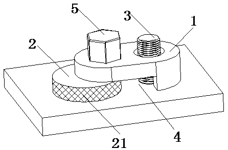
[0031] Specific embodiment 2 of the screw screw device of the present invention. The difference between this embodiment and the above-mentioned embodiment is only that: the above-mentioned rotating shaft and the eccentric wheel are rotationally matched. At this time, the power input section is not provided on the rotating shaft, and the eccentric wheel is provided with rotation The handle, by turning the handle to drive the eccentric wheel to rotate.

[0032] In other embodiments, the above-mentioned through hole may not be provided, and the screw can only be clamped by the first clamping portion and the second clamping surface. Of course, the receiving groove may not be provided, and only the through hole may be provided. The two clamping parts cooperate with the second clamping surface to clamp the screw; the above-mentioned eccentric wheel is a kind of cam. In other embodiments, the eccentric wheel may be another cam that meets the requirements of the clamping screw. Of course,...


PUM


Abstract

The invention relates to the field of screw twisting tools, in particular to a screw twisting device. The screw twisting device comprises a first clamping component, wherein the first clamping component is rotationally assembled with a second clamping component through a rotating shaft; a hook structure matched with a screw is arranged on the first clamping component; a first clamping surface is arranged on the hook structure; a second clamping surface is arranged on the second clamping component; the first clamping component and the second clamping component are matched, so that the first clamping surface and the second clamping surface clam the screw when the second clamping component is rotated to a set position. Compared with the conventional screw twisting device, the screw twisting device provided by the invention does not need to tap the screw, is convenient to operate and high in screw removing efficiency, and solves the problems that the conventional decapitated bolt removing structure is inconvenient to operate and is low in screw removing efficiency.

Description

Technical field [0001] The invention relates to the field of screw screwing tooling, in particular to a screw screwing device. Background technique [0002] In mechanical equipment, some bolt heads and screw rods are often disconnected during the process of disassembling bolts, and the screw rods are difficult to take out. In the prior art, the broken head bolts are taken out by a bolt takeout device. [0003] For example, the Chinese patent with the announcement number CN202707746U and the announcement date 2013.01.30 discloses a broken bolt extraction structure, which includes broken bolts threaded into the connecting piece, and the broken bolts are provided with the same center line as the broken bolts. The threaded hole of the threaded hole is threaded with a small bolt, and the threaded direction of the threaded hole is opposite to the threaded direction of the broken bolt. Use a wrench to clamp the small bolt and screw it into the threaded hole. Since the thread direction in...

Claims


Application Information

Patent Timeline
Patent Type & Authority Patents(China)
IPC IPC(8): B25B27/14
CPCB25B27/14B25B27/143
Inventor 郭东方杨葆鑫李琼可彭涛闫艳培李全和张军伟刘雅丽刘贯伟王鑫
Owner PINGGAO GRP
Why Eureka
Try Eureka