Gantry dual-driving system and error detection method thereof

A driving system and error detection technology, applied in manipulators, program-controlled manipulators, manufacturing tools, etc., can solve the problems of increased stroke error, poor machining accuracy, and inconsistent displacement at both ends of the gantry, eliminating errors and reducing control complexity. degree, avoid the effect of double-sided coupling control

Active Publication Date: 2017-01-04
易视智瞳科技(深圳)有限公司
View PDF7 Cites 2 Cited by
  • Summary
  • Abstract
  • Description
  • Claims
  • Application Information

AI Technical Summary

Problems solved by technology

[0003] However, due to the differences in the characteristics of the motors and screw rods at both ends of the gantry when they leave the factory, after a period of movement, the above structure is prone to problems such as inconsistent displacement at both ends of the gantry, increased stroke error, and poor machining accuracy.

Method used


Image

  • Gantry dual-driving system and error detection method thereof
  • Gantry dual-driving system and error detection method thereof
  • Gantry dual-driving system and error detection method thereof

Examples


Embodiment 1

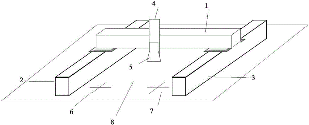
[0024] Please refer to figure 1 , is a structural schematic diagram of the gantry dual drive system provided by the first embodiment of the present invention, the system includes a beam 1 , a driving shaft 2 , a driven shaft 3 , and a main shaft 4 . The gantry dual drive system of the present invention is located on the XY operating plane 8. Specifically, the beam 1 is located in the X-axis direction, the driving shaft 2 and the driven shaft 3 are parallel to each other and both are located in the Y-axis direction, and the main shaft 4 is located in the Z-axis direction. A first marking point 6 and a second marking point 7 are provided on the XY operation plane 8, and the first marking point 6 and the second marking point 7 are located between the driving shaft 2 and the driven shaft 3, more specifically, the first The marking point 6 is close to the driving shaft 2 , and the second marking point 7 is close to the driven shaft 3 . The gantry dual drive system in this embodime...

Embodiment 2

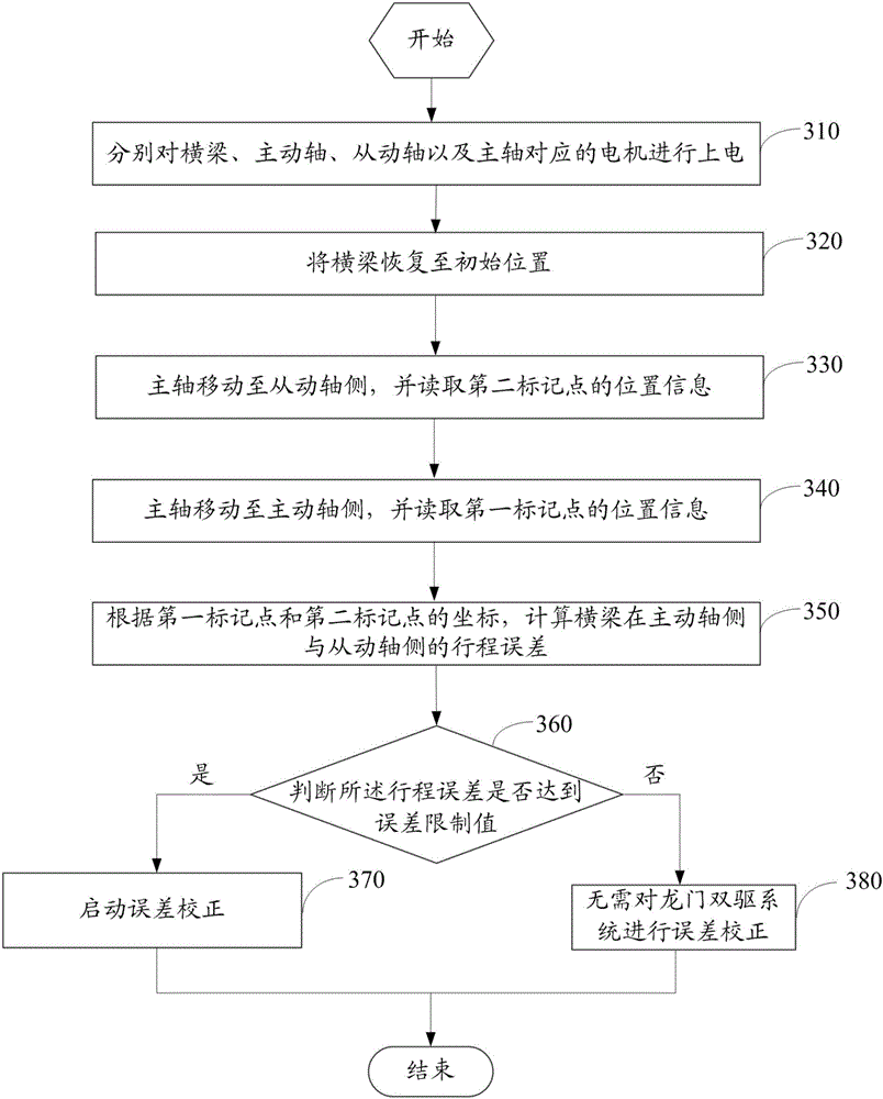
[0036] Please refer to image 3 , based on the gantry double drive system in the first embodiment, an error detection method of the gantry double drive system in the second embodiment of the present invention is proposed.

[0037] Step 310, respectively power on the motors corresponding to the beam, the driving shaft, the driven shaft and the main shaft.

[0038] Step 320, restoring the beam to its original position.


PUM


Abstract

The invention discloses a gantry dual-driving system and an error detection method thereof, and belongs to the technical field of automation control. The gantry dual-driving system comprises a cross beam, a driving shaft, a driven shaft, a main shaft, a first mark point and a second mark point, wherein the driving shaft and the driven shaft are parallel to each other, two ends of the cross beam are movably fixed on the main shaft and the driven shaft respectively, the first mark point and the second mark point are located between the driving shaft and the driven shaft, the main shaft is movably mounted on the cross beam, a visual system is arranged on the main shaft, and position information of the first mark point and that of the second mark point are read through the visual system respectively, so as to detect a journey error of the system. By virtue of mechanical characteristics of the dual gantry driving system per se, control complexity is reduced, not only is the characteristic of high measurement precision of the visual system exerted, but also the difficulty in double-side coupling control on the driving shaft and the driven shaft is avoided, and the gantry dual-driving system has a very high practical value.

Description

technical field [0001] The invention relates to the technical field of automation control, in particular to a gantry double drive system and an error detection method thereof. Background technique [0002] The gantry dual drive system is a common robot actuator in the automated production industry. It is synchronously driven by dual motors to obtain greater acceleration characteristics. [0003] However, due to the differences in the characteristics of the motors and screw rods at both ends of the gantry, after a period of movement, the above structure is prone to problems such as inconsistent displacement at both ends of the gantry, increased stroke error, and poor machining accuracy. This requires detecting and correcting the error of the gantry dual drive system every time it runs for a period of time to ensure that the machining accuracy of the system meets the requirements. [0004] Therefore, it is necessary to propose a gantry double drive system and its error detect...

Claims


Application Information

Patent Timeline
Patent Type & Authority Applications(China)
IPC IPC(8): B25J9/02B25J9/16
CPCB25J9/026B25J9/1653
Inventor 时曦黄卜夫王星华
Owner 易视智瞳科技(深圳)有限公司
Why Eureka
Try Eureka