
Device for Measuring Convergence Displacement and Top Subsidence Using Fiber Bragg Grating Sensor

A fiber grating and measuring device technology, which is applied in the direction of using optical devices, measuring devices, and optical instruments for testing, etc., can solve the problems of length displacement measurement value error, reduced measurement value precision, measurement precision limitation and other problems, so as to improve the measurement accuracy. Excellent effect of precision, error prevention, and measurement resolution

Active Publication Date: 2019-05-10
FBG KOREA INC
View PDF5 Cites 0 Cited by
  • Summary
  • Abstract
  • Description
  • Claims
  • Application Information

AI Technical Summary

Problems solved by technology

[0012] However, with the installation of fiber grating sensors on a plane, conventional convergent settlement and top settlement measurement devices including Patent Document 1 and Patent Document 2 have limitations in the precision of two-dimensional (2D) and three-dimensional (3D) measurements.
[0013] In addition, in the installation process of the conventional convergent settlement and top settlement measuring devices, if there is play due to interference formed on the object to be installed, it is difficult to install and the precision of the measured value is significantly reduced. The problem
[0014] Moreover, with the installation of the angular displacement sensor on the strain sensor, the prior art convergence settlement and top settlement measurement devices have the problem of generating errors in the measured value of the length displacement due to the load of the angular displacement sensor.

Method used


Image

  • Device for Measuring Convergence Displacement and Top Subsidence Using Fiber Bragg Grating Sensor
  • Device for Measuring Convergence Displacement and Top Subsidence Using Fiber Bragg Grating Sensor
  • Device for Measuring Convergence Displacement and Top Subsidence Using Fiber Bragg Grating Sensor

Examples


Embodiment Construction

[0042] Hereinafter, a device and method for measuring convergence displacement and top subsidence using a fiber grating sensor according to preferred embodiments of the present invention will be described in detail with reference to the accompanying drawings.

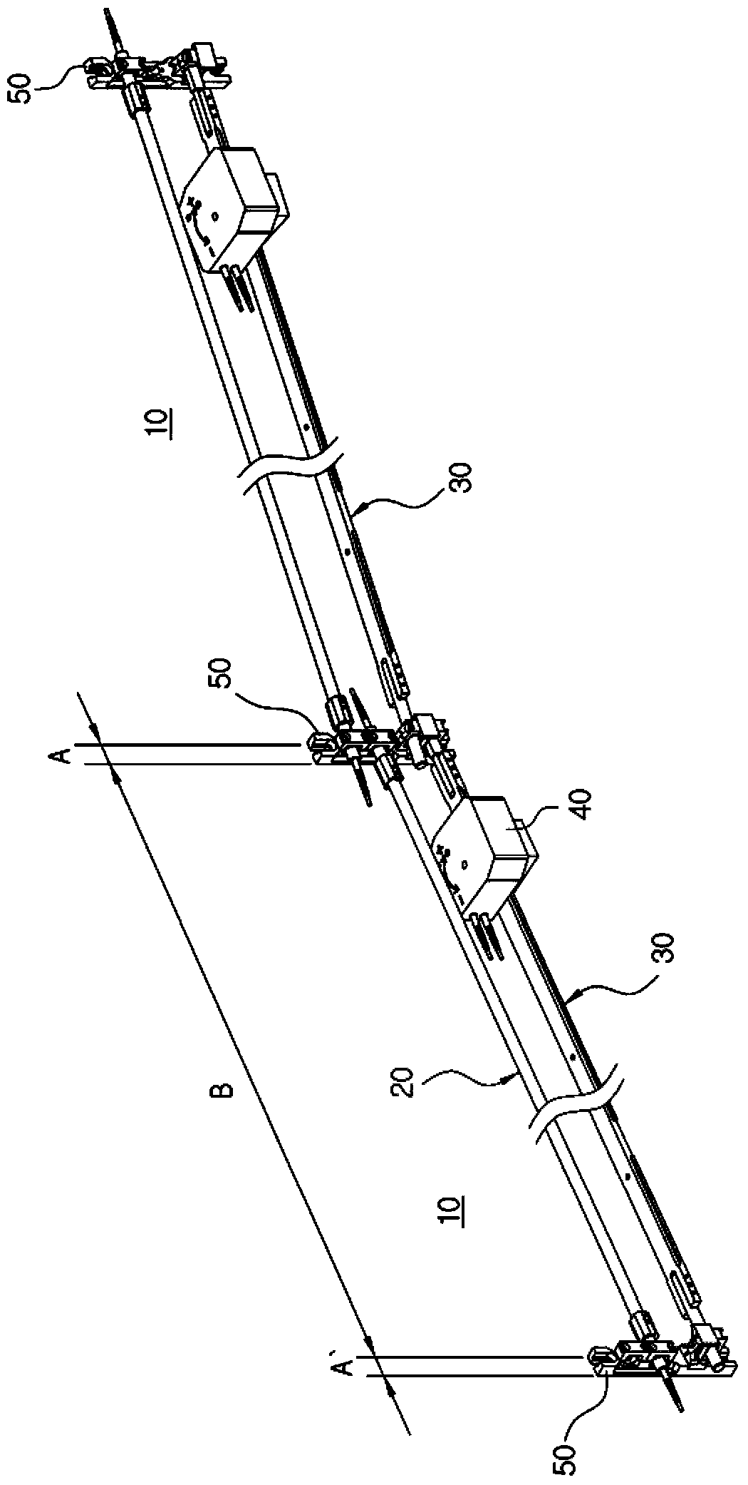
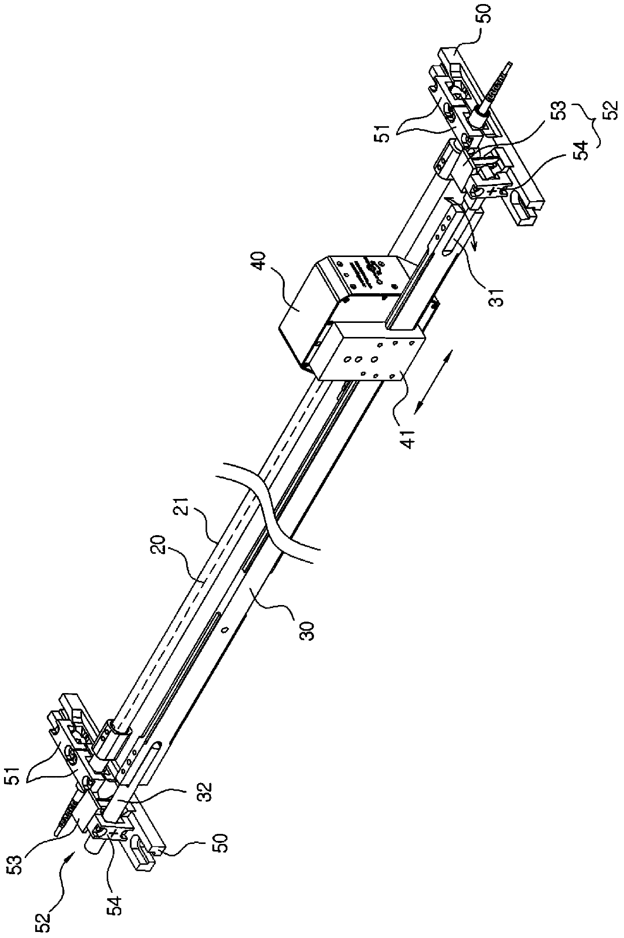
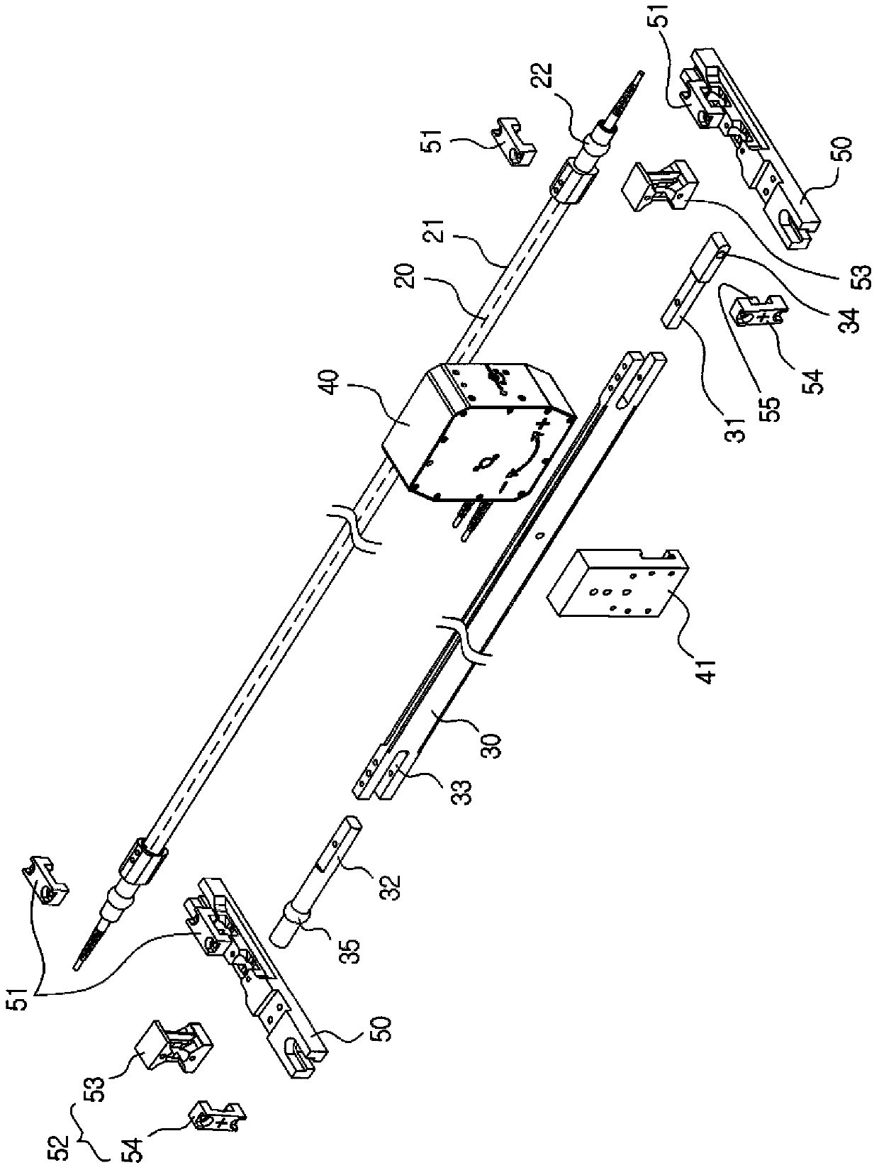
[0043] figure 1 It is a perspective view of the convergent displacement and top settlement measuring device utilizing the fiber grating sensor in the preferred embodiment of the present invention, figure 2 and image 3 respectively figure 1 The enlarged perspective view and partial enlarged perspective view of the unit fiber grating sensor module shown.

[0044] Such as figure 1 As shown, the device for measuring convergence displacement and top subsidence using a fiber grating sensor in a preferred embodiment of the present invention includes a plurality of unit fiber grating sensor modules (hereinafter referred to as "sensor modules") 10, and the above-mentioned plurality of unit fiber grating sensor modules 10 have...


PUM


Abstract

The invention relates to a device for measuring convergence displacement and top settlement using fiber grating sensors, which includes: a plurality of unit fiber grating sensor modules. The plurality of unit fiber grating sensor modules have a preset length and are continuously connected for use; The unit fiber Bragg grating sensor module includes: a fiber Bragg grating strain sensor, which is installed inside the protective tube for detecting length changes; a setting component, which is arranged side by side on one side of the above-mentioned protection tube; and a fiber Bragg grating angular displacement sensor, which is arranged on the above-mentioned setting component. For measuring angular displacement, the present invention continuously measures two-dimensional or three-dimensional convergence displacement and top settlement, thereby achieving the following effects: multiple unit fiber grating sensor modules can be continuously installed on the measurement object to measure cross-sectional deformation based on The movement distance and angular displacement of the coordinate points can be accurately measured, so that the convergence displacement and top settlement can be accurately measured.

Description

technical field [0001] The present invention relates to a device for measuring convergence displacement and top settlement using a fiber bragg grating sensor (FIBER BRAGG GRATING SENSOR). Convergence displacement and top settlement measuring device. Background technique [0002] When measuring the convergence displacement of the tunnel, if only the change in the longitudinal direction is measured on the section, in terms of the deformation characteristics of the lining, since the directionality of the coordinates cannot be known after the deformation occurs, it is useful to know whether the tunnel shrinks or not. Difficulty measuring the exact convergence displacement before dilation. [0003] Therefore, the conventional tunnel convergence displacement and top settlement measurement method uses the lining that penetrates the tunnel and fills the measurement sensor to determine whether expansion or contraction occurs, or uses a displacement sensor and an angle sensor for mea...

Claims


Application Information

Patent Timeline
Patent Type & Authority Patents(China)
IPC IPC(8): G01B11/02G01C5/00
CPCG01B11/02G01C5/00G01M11/085G01D5/35316G01B11/16G01B11/165G01B11/18G01M5/005G01L1/246G01B11/14G01B11/26G01L5/00
Inventor 李锦锡
Owner FBG KOREA INC
Learn More