
A vehicle driving safety control system

A control system and driving safety technology, applied in the field of vehicle driving safety control system, can solve the problems of easy traffic accidents, unfavorable safety, brake failure, etc., and achieve the advantages of convenient ramp start operation, avoiding vehicle accidents, and improving safety performance Effect

Active Publication Date: 2018-10-30
周茂敬
View PDF6 Cites 0 Cited by
  • Summary
  • Abstract
  • Description
  • Claims
  • Application Information

AI Technical Summary

Problems solved by technology

Under normal circumstances, the hand brake, clutch and accelerator should be well coordinated when starting, so that the car can start without slipping; Difficulties are greater, the right foot has to step on both the brake and the accelerator, it is difficult to control, especially the driver with insufficient driving experience is likely to be in a hurry, and traffic accidents are likely to occur at this time
In addition, some drivers used the brake improperly and controlled improperly when going down a long slope, and the brakes failed due to flameout and coasting, causing the vehicle to lose control and lead to tragedy.
At present, the hand brake and foot brake set on tractors and transport vehicles all act on the brakes. When the brakes fail or the air pressure is insufficient, the car has no other backup emergency braking system, which is not conducive to safety.

Method used


Image

  • A vehicle driving safety control system
  • A vehicle driving safety control system
  • A vehicle driving safety control system

Examples


Embodiment Construction

[0024] The implementation of the present invention will be described in detail below in conjunction with the accompanying drawings.

[0025] A vehicle driving safety control system, such as figure 1 As shown, it includes an ignition switch 1, a battery E and a driving controller 2. The driving controller 2 can be configured separately for the system, or the original controller of the car can be used. The battery E is connected to the coil of a relay K through the ignition switch 1, and the two normally open contacts of the relay K are respectively connected to the positive pole of the battery and the power supply terminal of the driving controller. When the car is ignited, the power supply circuit of the controller is connected. The system newly sets up the slope start anti-slip control system and the driving emergency braking control system. In order to complete the work of the two systems, it is necessary to make some improvements to the vehicle transmission shaft, and insta...


PUM


Abstract

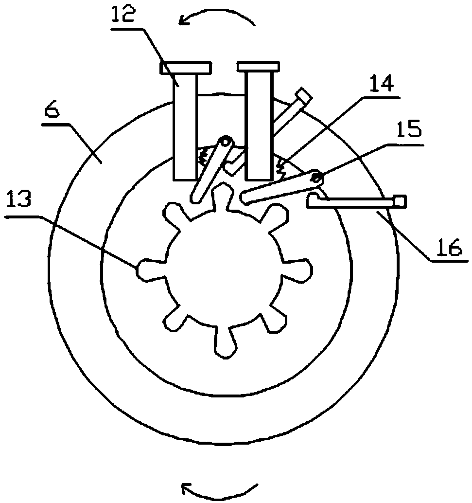
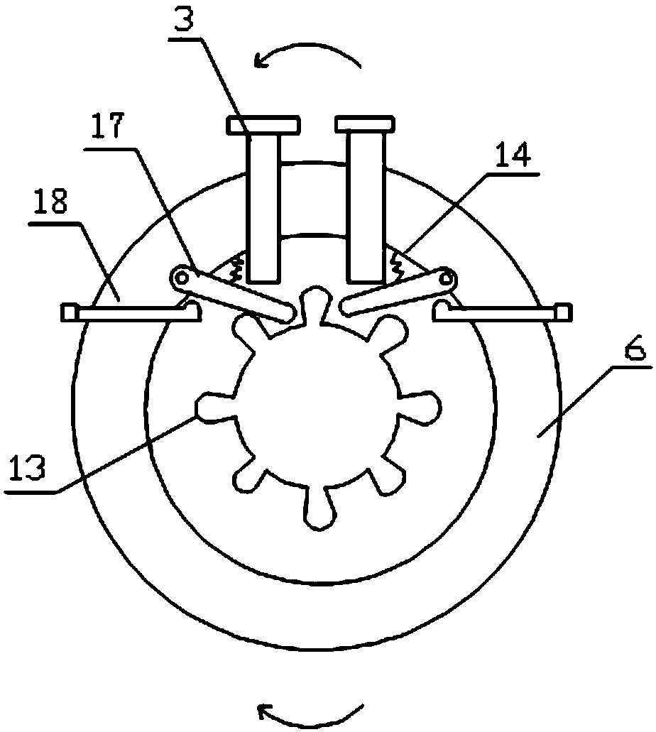
The invention relates to the technical field of automobile braking, in particular to a vehicle driving safety control system. The system comprises a controller, a hill-start backward sliding prevention control system, a driving emergency brake control system, a reverse tooth gear shaft sleeving an automobile transmission shaft and reverse teeth on the reverse tooth gear shaft, wherein the hill-start backward sliding prevention control system comprises a backward sliding prevention switch, a first-gear switch, a gradient sensor and a backward sliding prevention electromagnetic valve; when the condition is met, the controller electrifies the electromagnetic valve, armature pusher rods moves downwards to press a lock rod to press against the reverse teeth and prevent the transmission shaft from rotating anticlockwise; the driving emergency brake control system comprises a pedal position sensor, a pusher rod extreme position switch, a reverse switch, a wheel speed sensor and an emergency brake electromagnetic valve; during electrification under the condition, the two armature pusher rods press the reverse teeth from the two sides to prevent the transmission shaft from rotating clockwise and anticlockwise. The vehicle driving safety control system has functions of prevention of a vehicle from sliding backwards and automatic emergency braking, so that the safety of the vehicle can be improved, and vehicle accidents are effectively avoided.

Description

technical field [0001] The invention relates to the technical field of automobile braking, in particular to a vehicle driving safety control system. Background technique [0002] Cars will encounter various situations during driving, such as starting on an uphill section and failure of service brakes. In these special situations, improper handling can easily lead to vehicle accidents and endanger personal safety. When starting uphill, if the operation is improper, the car may slip backwards, especially under heavy load, when the hand brake performance is not good. In order to avoid this from happening, it is necessary to constantly practice the driving skills of the car starting on a hill. Under normal circumstances, the hand brake, clutch and accelerator should be well coordinated when starting, so that the car can start without slipping; Difficulty is greater, the right foot has to step on the brake and also step on the gas pedal, it is difficult to control, especially t...

Claims


Application Information

Patent Timeline
Patent Type & Authority Patents(China)
IPC IPC(8): B60T1/06B60T7/04B60T7/12B60T13/74B60R16/023
CPCB60K17/08B60R16/0232B60T13/746B60T2201/04B60T2220/04B60T2250/04B60T2260/00
Inventor 周茂敬
Owner 周茂敬
Learn More