
Automatic Rebar Binding Machine

A steel bar binding and automatic technology, applied in the direction of construction, building structure, building material processing, etc., can solve the problems of environmental protection, high construction cost, poor applicability, etc.

Active Publication Date: 2018-08-14
李振飞
View PDF7 Cites 2 Cited by
  • Summary
  • Abstract
  • Description
  • Claims
  • Application Information

AI Technical Summary

Problems solved by technology

Although using an electric steel bar binding machine to bind steel bars can achieve fast and continuous steel bar binding operations to a certain extent, there are also some defects in this operation method, such as: ①The electric steel bar binding machine is expensive because of its complex structure. High, resulting in high construction costs; ②The current electric steel bar binding machines on the market are relatively large in size, heavy in weight, and inflexible, and the labor intensity is high for workers to operate for a long time; ③Requires regular charging, poor applicability, and battery Waste, not environmentally friendly; ④The electric steel bar binding machine only simply tightens the steel bars during the binding operation, so the binding strength of the steel bars is not good

Method used


Image

  • Automatic Rebar Binding Machine
  • Automatic Rebar Binding Machine
  • Automatic Rebar Binding Machine

Examples


Embodiment Construction

[0092] Embodiments of the present invention will be described in detail below in conjunction with the accompanying drawings.

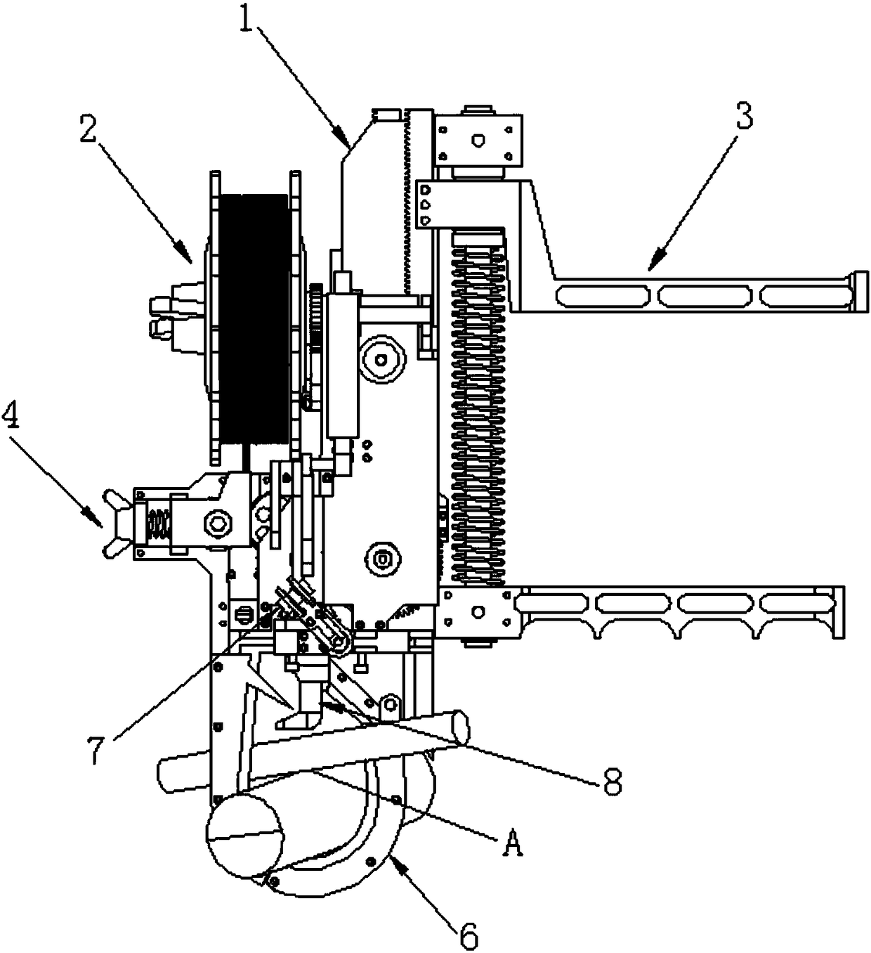
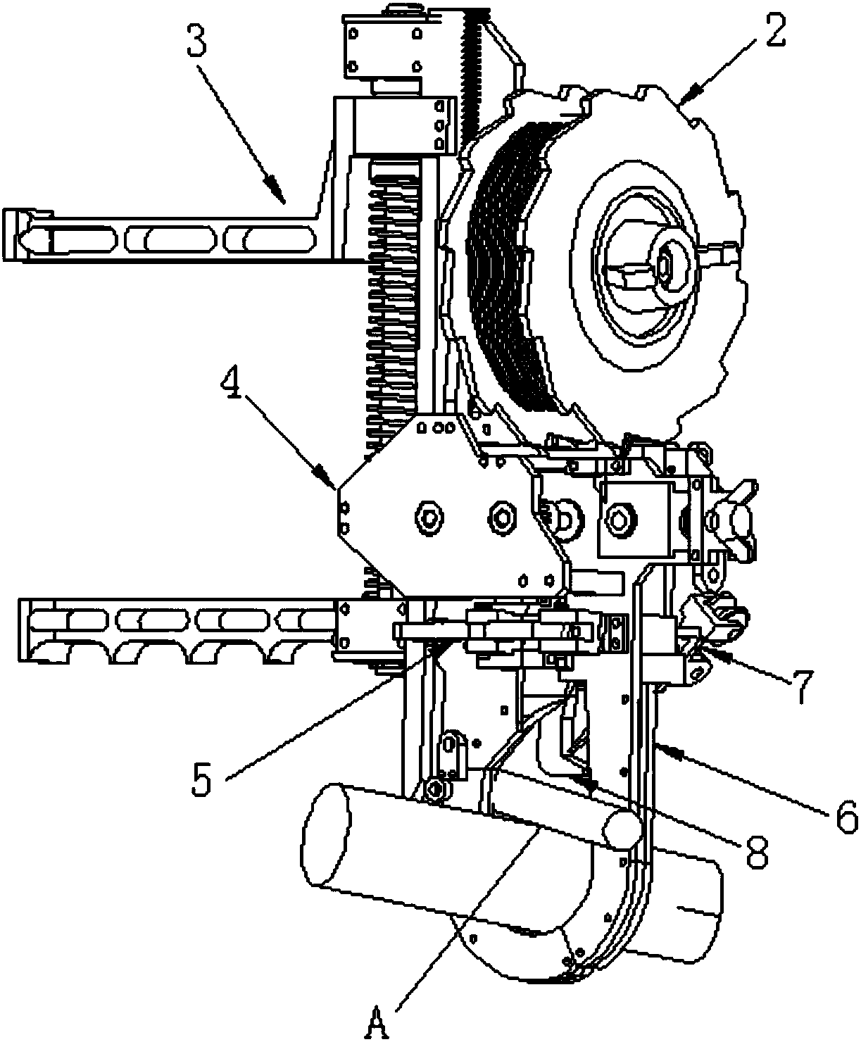
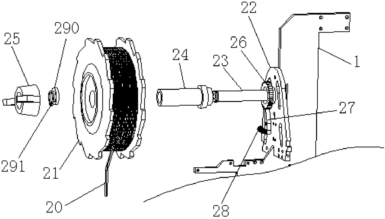
[0093] An automatic steel bar binding machine provided by the present invention includes a frame 1, and a wire binding mechanism 2, a power mechanism 3, a wire feeding mechanism 4, a wire cutting mechanism 5, and jaws respectively arranged on the frame 1. And guiding mechanism 6, twisted wire mechanism 7 and twisted wire mechanism 8, wherein, described wire-tie disc mechanism 2 has a wire-tie disc 21 for winding 20 of wire-tie, and wire-tie 20 can take single-track wire or double-track wire or The winding method of the three wires is wound on the wire-tie disc 21, and the wire-tie disc 21 is rotatably connected to the frame 1; the power mechanism 3 can drive the action of the wire feeding mechanism 4, and by means of the The action of the wire mechanism 4 drives the wire binding 20 to walk, that is, wire walking; the jaws and the guide mechanism 6 have...


PUM


Abstract

The invention discloses an automatic reinforcing steel bar binding machine. The automatic reinforcing steel bar binding machine comprises a machine frame, a wire binding disc mechanism, a power mechanism, a wire conveying mechanism, a wire cutting mechanism, a jaw and guiding mechanism, a wire bending mechanism and a wire twisting mechanism, wherein the wire binding disc mechanism, the power mechanism, the wire conveying mechanism, the wire cutting mechanism, the jaw and guiding mechanism, the wire bending mechanism and the wire twisting mechanism are arranged on the machine frame; and the seven mechanisms are deployed reasonably, and on the one hand, operation such as wire conveying, wire cutting, wire bending and wire twisting can be achieved rapidly and continuously through one hand, the working efficiency is greatly improved, even untrained workers can easily and proficiently operate, labor cost is reduced, and one the other hand, binding is tight to achieve the effect of manual binding. In addition, the automatic reinforcing steel bar binding machine is small and exquisite, portable, flexible, low in cost, high in adaptability, free from charging, waterproof, adaptable to severe environment and easy to promote and popularize.

Description

technical field [0001] The invention relates to the technical field of building construction auxiliary fixtures, and specifically provides an automatic steel bar binding machine. Background technique [0002] Reinforced concrete is widely used in building structures. Before pouring concrete, formwork is first carried out, that is, the steel bars are fixed into the desired structural shape with iron wires, and then the formwork is used to cover the outside of the steel bar skeleton, and finally the concrete is poured in, and the formwork is removed after curing to reach the strength standard. That is reinforced concrete. [0003] At present, the binding of steel bars in the reinforced concrete construction process mainly uses steel bar binding hooks, or uses electric steel bar binding machines. (1) Bind the steel bars with the steel bar tie hook; first cut the whole plate of tie wire to a certain length. During the operation, the worker holds the wire in one hand and the ho...

Claims


Application Information

Patent Timeline
Patent Type & Authority Patents(China)
IPC IPC(8): E04G21/12
CPCE04G21/123
Inventor 李振飞
Owner 李振飞
Learn More