Well drilling thief zone location identification method based on multi-message fusion

A multi-information fusion and identification method technology, applied in the field of drilling leakage layer identification based on multi-information fusion, can solve the problems of physical properties and fracture parameters without detailed calculation models, insufficient discrimination accuracy, physical properties and fracture parameter calculations, etc.

Active Publication Date: 2017-01-04
CHINA UNIV OF PETROLEUM (EAST CHINA)
View PDF5 Cites 33 Cited by
  • Summary
  • Abstract
  • Description
  • Claims
  • Application Information

AI Technical Summary

Problems solved by technology

This method can accurately identify the leakage layer, but it cannot describe the properties of the leakage layer, such as leakage channel property parameters such as leakage layer lithology, porosity and permeability.
[0004] The document published earlier by the applicant ("Discussion on the Method of Determining the Lost Loss Layer", Chen Ganghua et al., Drilling Fluid and Completion Fluid, Volume 26, No. 2, March 2009) has studied the determination of the lost circulation layer However, due to the limited factors considered, only the pressure is considered, and the lithology, physical properties and fracture parameters of the formation where leakage may occur are not carefully calculated. For the formation lithology analysis, the logging lithology results are directly applied, but generally There are large errors between the logging lithology results and the actual formation lithology; there is no detailed calculation model for the calculation of physical properties and fracture parameters, so the accuracy of the judgment of the leakage layer is not enough, especially in fracture-developed formations. There are deficiencies
Moreover, it is impossible to analyze and describe the leakage mechanism, etc.

Method used


Image

  • Well drilling thief zone location identification method based on multi-message fusion
  • Well drilling thief zone location identification method based on multi-message fusion
  • Well drilling thief zone location identification method based on multi-message fusion

Examples


Embodiment Construction

[0052] The technical solutions in the embodiments of the present invention will be clearly and completely described below. Obviously, the described embodiments are only some of the embodiments of the present invention, but not all of them. Based on the embodiments of the present invention, all other embodiments obtained by persons of ordinary skill in the art without making creative efforts belong to the protection scope of the present invention.

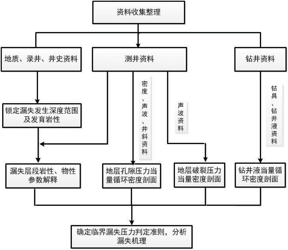
[0053] The embodiment of the present invention provides a method for identifying leakage layers in drilling based on multi-information fusion, and the specific steps include:

[0054] S1 According to well history data and mud logging comprehensive record data, lock the depth range of leakage and the lithology developed in the formation within the depth range, and then analyze and narrow the range according to the response characteristics of well logging curves.

[0055] In this step, in the fractured formation, the natural gamma ray...


PUM


Abstract

The invention provides a well drilling thief zone location identification method based on multi-message fusion, and belongs to the field of well drilling exploration. A thief zone can be accurately determined and thief zone property parameters can be accurately calculated according to essential conditions for leakage. The well drilling thief zone location identification method based on multi-message fusion includes the specific steps that (1) according to drilling fluid summaries and comprehensive logging record data, the leakage depth range is locked, and the developed lithology of a formation within the depth range is locked; (2) lithology and physical property parameters within the leakage depth range locked in the first step are explained and calculated through logging information and geologic information; (3) the equivalent circulating density of drilling fluid, the formation pore pressure equivalent density and the formation fracture pressure equivalent density are calculated according to logging and engineering information; and (4) data obtained in the step (1), the step (2) and the step (3) are sorted to draw a comprehensive result map, thief zone location identification is carried out through the comprehensive result map, and the leakage mechanism is analyzed.

Description

technical field [0001] The invention relates to the field of drilling exploration, in particular to a method for identifying lost layers in drilling based on multi-information fusion. Background technique [0002] Lost circulation is a complex downhole situation in which various working fluids (including drilling fluid, cement slurry, completion fluid, etc.) flow into the formation under the action of pressure difference during drilling and other downhole operations. One of the common technical problems. Lost circulation is very harmful: it causes a large amount of working fluid to leak into the formation, directly causing huge material losses, delaying drilling time, and prolonging the drilling cycle; lost circulation can also damage the productivity of the reservoir, interfere with geological logging work, and even It will cause various downhole complex situations such as drill sticking, blowout, and well collapse. Therefore, it is of great significance to identify the l...

Claims


Application Information

Patent Timeline
Patent Type & Authority Applications(China)
IPC IPC(8): E21B47/10E21B49/00
CPCE21B47/10E21B49/00
Inventor 陈钢花邱正松周杨
Owner CHINA UNIV OF PETROLEUM (EAST CHINA)
Why Eureka
Try Eureka