
Treatment method and device for gas compressor communicating type contraction joint casing

A casing treatment and contraction joint technology, which is applied to machines/engines, components of pumping devices for elastic fluids, mechanical equipment, etc., can solve problems such as engine flameout and component damage, and reduce flow blockage and inhibit Effect of low energy leak flow and enhanced blow-off capability

Active Publication Date: 2017-01-04
INST OF ENGINEERING THERMOPHYSICS - CHINESE ACAD OF SCI
View PDF7 Cites 2 Cited by
  • Summary
  • Abstract
  • Description
  • Claims
  • Application Information

AI Technical Summary

Problems solved by technology

When the compressor enters an unstable working condition, the air flow in the compressor pulsates along the circumferential or axial direction, which may cause the engine to stall and cause serious damage to components

Method used


Image

  • Treatment method and device for gas compressor communicating type contraction joint casing
  • Treatment method and device for gas compressor communicating type contraction joint casing
  • Treatment method and device for gas compressor communicating type contraction joint casing

Examples


Embodiment Construction

[0035] In order to make the object, technical solution and advantages of the present invention clearer, the present invention will be further described in detail below with reference to the accompanying drawings and examples. It should be noted that the following descriptions are only preferred embodiments of the present invention, and therefore do not limit the protection scope of the present invention.

[0036] It should be noted that implementations not shown or described in the accompanying drawings are forms known to those of ordinary skill in the art. In addition, the directional terms mentioned in the following embodiments, such as "upper", "lower", "front", "backward", "left", "right", "top", "bottom", etc., are only for reference The orientation of the graph. Accordingly, the directional terms are used to illustrate and not to limit the invention.

[0037] The purpose, technical solutions and advantages of the present invention will be described in detail below in c...


PUM


Abstract

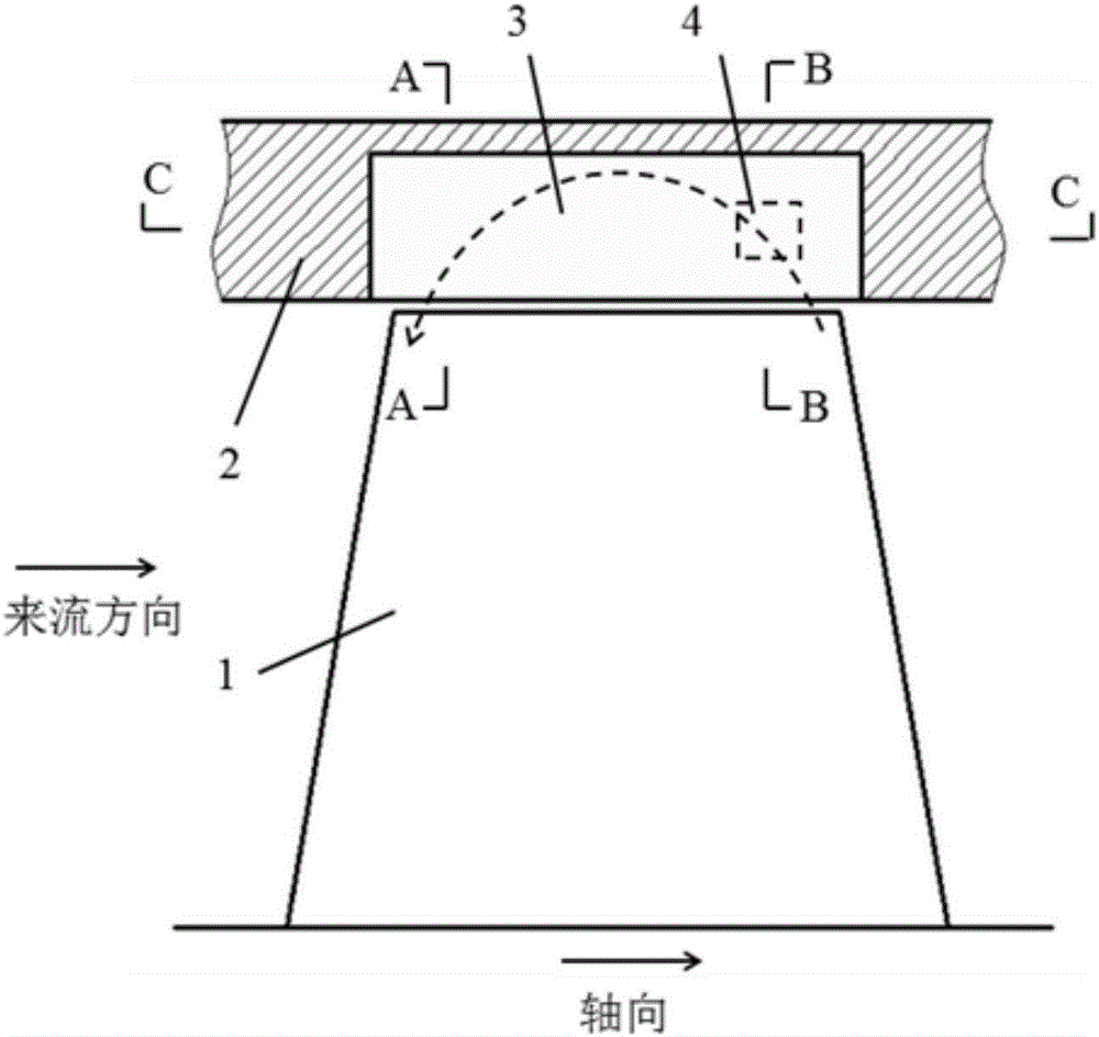
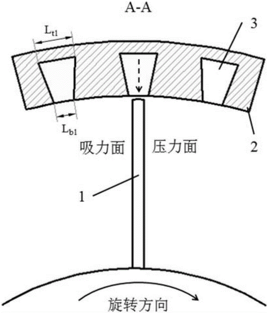
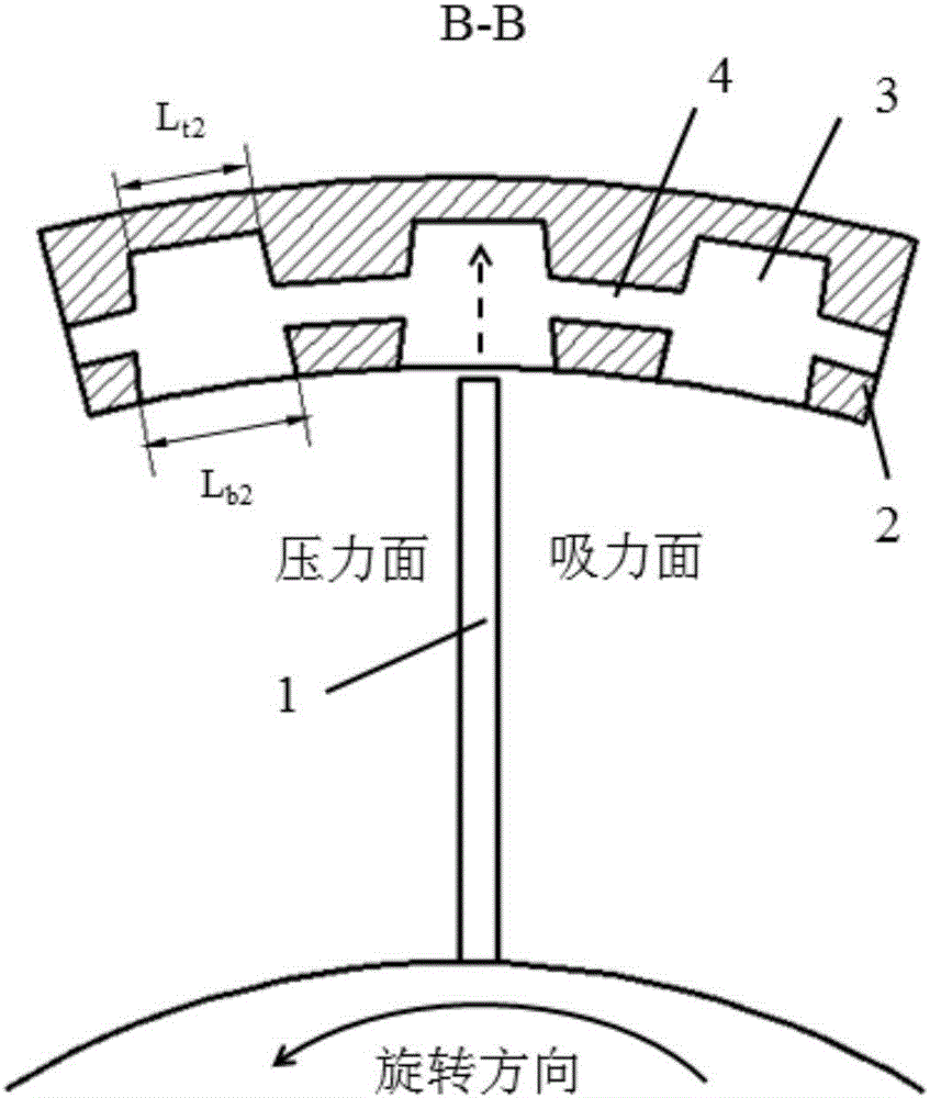
The invention discloses a treatment method and device for a gas compressor communicating type contraction joint casing. The wall face of the gas compressor casing is provided with a plurality of dispersed contraction joints in the circumferential direction, and the joint depth direction is in the radial direction of a gas compressor. The sectional area of the contraction joints increases gradually in the axial direction, and the ratio of the rear end width to the front end width of the contraction joints is lowered gradually in the radial direction. Meanwhile, the sectional area of the rear portions of the contraction joints decreases gradually in the radial direction, and the sectional area of the front portions of the contraction joints increases gradually. Connection channels are formed between the rear portions of all the contraction joints, and thus the dispersed contraction joints communicate with one another. After accelerated in radial and axial contraction runners in the joints, sub-sound gas flow entering the contraction joints from the downstream parts of blade channels is jetted into the blade channels again from the upstream parts, and low-energy leakage flow at the blade tops can be blown away. Fluid in all the contraction joints can be exchanged through the connection channels, the backflow quantity in the contraction joints in different positions can be adjusted automatically according to the circumferential pressure distribution at the blade tops, thus blocking of different circumferential positions can be reduced effectively, and the stable work range of the gas compressor is increased.

Description

technical field [0001] The invention relates to a flow control method and device for casing treatment of a compressor, in particular to a flow control method and device for a connected contraction joint casing, which can be used to improve the stable working range of a compressor and belongs to the field of impeller machinery. Background technique [0002] The ever-increasing demand for air transportation puts forward higher requirements on the thrust-to-weight ratio of aero-engines. With the development of aero-engines toward higher thrust-to-weight ratios, the number of compressor stages is gradually reduced, and the single-stage load continues to increase. The relatively high Mach number of the inlet of the high-load compressor is large, and the interaction between the shock wave and the boundary layer is likely to induce large-area flow separation. At the same time, the pressure difference between the pressure surface and the suction surface of the blade tip of the high...

Claims


Application Information

Patent Timeline
Patent Type & Authority Applications(China)
IPC IPC(8): F04D29/40
CPCF04D29/403
Inventor 周小勇赵庆军崔伟伟赵巍徐建中
Owner INST OF ENGINEERING THERMOPHYSICS - CHINESE ACAD OF SCI
Learn More