Buffer

A buffer and elastic body technology, applied in the field of non-hydraulic, non-pneumatic, and non-hydraulic buffers, can solve the problems of high machining accuracy, complex design of hydraulic buffers, and high requirements for accessories

Active Publication Date: 2017-01-04
LIAN YANG PLASTIC (SHEN ZHEN) CO LTD
View PDF4 Cites 1 Cited by
  • Summary
  • Abstract
  • Description
  • Claims
  • Application Information

AI Technical Summary

Problems solved by technology

[0006] Most of the existing buffers use hydraulic buffers. In theory, conventional hydraulic buffers can also achieve their purpose. However, in practice, the design of hydraulic buffers is relatively complicated, and it has high requirements for accessories and high processing accuracy.
In addition, for child safety seats, when the weight of the child is different, the effect of the hydraulic shock absorber is also different, and it is not effective in cushioning the instantaneous large impact force. Therefore, the conventional hydraulic shock absorber cannot meet the demand. Develop a new type of buffer that is reliable, easy to process, and easy to control

Method used


Image

  • Buffer
  • Buffer
  • Buffer

Examples


Embodiment Construction

[0032] The following examples are further explanations and supplements to the present invention, and do not constitute any limitation to the present invention.

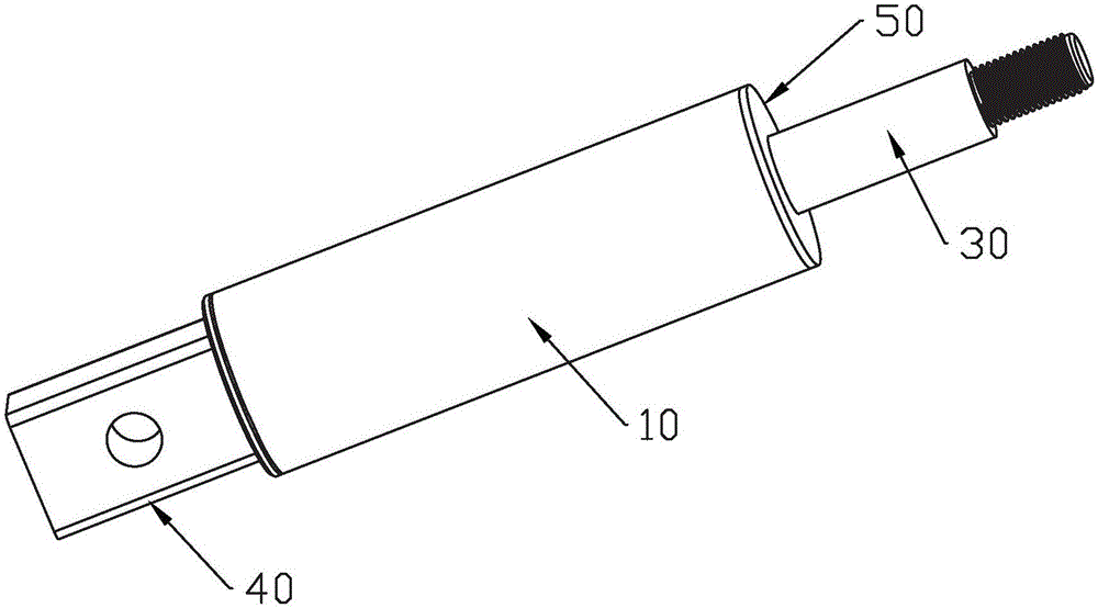
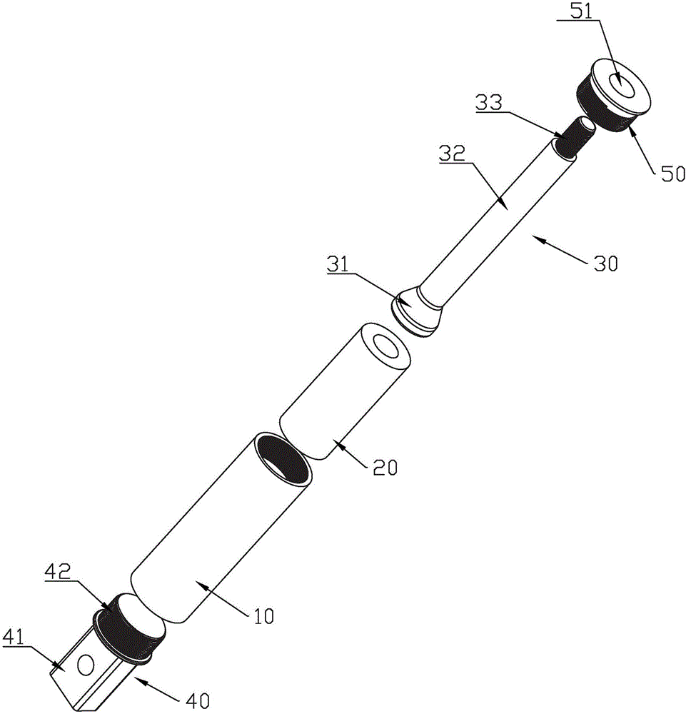
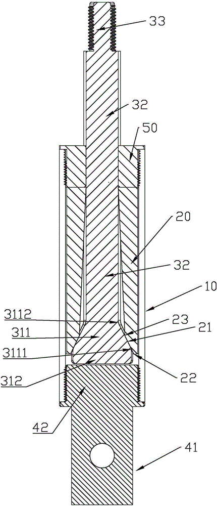
[0033] Such as Figure 1 to Figure 8 As shown, the buffer 1 of the present invention includes an outer shell 10 , an elastic body 20 , a movable shaft 30 , and a connecting piece 40 . Further, it may also include an end cap 50 .

[0034] Such as Figure 1 ~ Figure 3 As shown, the outer casing 10 is cylindrical, and in this embodiment, it is cylindrical. The outer casing 10 can be configured to be open at both ends, or can be configured to be open at one end, so that it can be inserted into the elastic body 20 .

[0035] Such as Figure 2 ~ Figure 3As shown, the elastic body 20 is used for cushioning, and it is cylindrical, and its shape is the same or similar to that of the outer casing 10 , and in this embodiment, it is cylindrical. Both ends of the elastic body 20 are open, and are used for movably setting the ...


PUM


Abstract

A buffer comprises an outer shell, an elastic body and a movable shaft, wherein the outer shell and the elastic body are cylindrical; two ends of the elastic body are open; the elastic body is arranged in the outer shell in a sleeving manner; the movable shaft is arranged in the elastic body in a sleeving manner, and comprises a head part and a rod body part which are integrally connected or integrally formed; the head part of the movable shaft penetrates through an end part of the elastic body, and extends out of the elastic body or embedded in the end part of the elastic body; the rod body part penetrates through the other end of the elastic body, and extends out of the elastic body; the size of the rod body part is so proper that the rod body part can move in the elastic body in the length direction; and the size of the head part is so proper that the head part can enter the elastic body but cannot be separated out of the elastic body. When impact is caused, the head part of the movable shaft presses the elastic body, and is buffered by the elastic body due to elasticity, so that the purpose of buffering is realized. The buffer has the advantages that the structure is simple; the use is convenient; the processing, the production and the control are easy; and the practicability is strong.

Description

[0001] 【Technical field】 [0002] The invention relates to a buffer, in particular to a non-hydraulic, non-air pressure and non-oil pressure buffer. [0003] 【Background technique】 [0004] The driving speed of the car is very fast. Once a collision occurs, the body stops moving, and the passenger's body will continue to move forward due to inertia, and will collide with the body in the car. In severe cases, the windshield may be smashed and fly forward out of the window. To prevent similar injuries in a crash, cars are equipped with seat belts. If the seat belt is pulled quickly, for example, when a collision occurs and the deceleration is sharp, the clip inside the seat belt device will be taken out by the centrifugal force due to the rapid rotation of the seat belt roller, thereby quickly locking the seat belt and fixing the person on the seat. On the chair, thereby ensuring the safety of the driver and passengers. Although seat belts have improved the safety of drivers an...

Claims


Application Information

Patent Timeline
Patent Type & Authority Applications(China)
IPC IPC(8): F16F7/104B60R22/28
CPCB60R22/28F16F7/104
Inventor 李邱宗
Owner LIAN YANG PLASTIC (SHEN ZHEN) CO LTD
Why Eureka
Try Eureka