Flue gas recirculation boiler structure of combustor
A flue gas recirculation and burner technology, applied in combustion methods, combustion types, combustion equipment, etc., can solve problems such as affecting normal operation, reducing thermal efficiency by 1% to 2.5%, and destructive consequences.
- Summary
- Abstract
- Description
- Claims
- Application Information
AI Technical Summary
Problems solved by technology
Method used
Image
Examples
Embodiment Construction
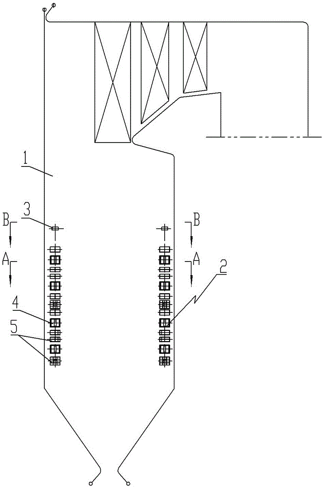
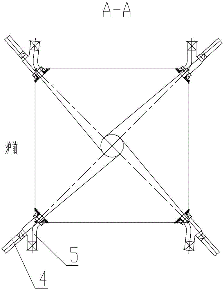
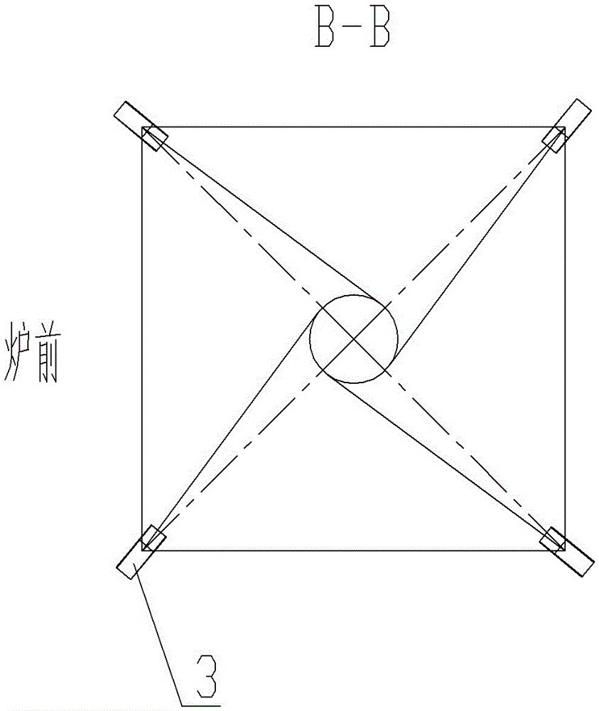
[0011] See figure 1 , figure 2 , image 3 As shown, a burner flue gas recirculation boiler structure includes a furnace 1, a main burner 2 is installed on the furnace 1, the main burner 2 includes a primary air interface 4 and a secondary air interface 5, the primary air interface 4 and The air outlet direction of the secondary air interface 5 is tangent to the tangent circle of the main burner 2, and a flue gas recirculation nozzle 3 is arranged above the main burner 2. The flue gas recirculation nozzle 3 includes four, four The air outlet directions of the flue gas recirculation nozzles 3 are respectively tangent to the tangent circle of the main burner 3 . There are four groups of primary air interfaces 4 arranged from bottom to top, and a group of secondary air interfaces 5 are arranged at the upper and lower ends of each group of primary air interfaces 4, and each group of primary air interfaces 4 and secondary air interfaces 5 includes four uniformly arranged indivua...
PUM
 Abstract
Description
Claims
Application Information
 - R&D
- Intellectual Property
- Life Sciences
- Materials
- Tech Scout
- Unparalleled Data Quality
- Higher Quality Content
- 60% Fewer Hallucinations
Browse by: Latest US Patents, China's latest patents, Technical Efficacy Thesaurus, Application Domain, Technology Topic, Popular Technical Reports.
© 2025 PatSnap. All rights reserved.Legal|Privacy policy|Modern Slavery Act Transparency Statement|Sitemap|About US| Contact US: help@patsnap.com


