
Ultrasonic C scanning path correcting method taking workpiece eccentric clamping errors into consideration

A technology of scanning path and correction method, which is applied in the direction of material analysis, measuring device and instrument using sonic/ultrasonic/infrasonic waves, which can solve the problems of decreased detection accuracy and clamping error.

Active Publication Date: 2017-01-04
CENT SOUTH UNIV
View PDF4 Cites 8 Cited by
  • Summary
  • Abstract
  • Description
  • Claims
  • Application Information

AI Technical Summary

Problems solved by technology

[0007] In order to solve the technical problem that the current workpiece clamping error causes the detection accuracy to drop, the technical solution of the present invention is:

Method used


Image

  • Ultrasonic C scanning path correcting method taking workpiece eccentric clamping errors into consideration
  • Ultrasonic C scanning path correcting method taking workpiece eccentric clamping errors into consideration
  • Ultrasonic C scanning path correcting method taking workpiece eccentric clamping errors into consideration

Examples


Embodiment Construction

[0047]The present invention will be described in further detail below in conjunction with the accompanying drawings and embodiments. The following examples are used to illustrate the present invention, but should not be used to limit the scope of the present invention.

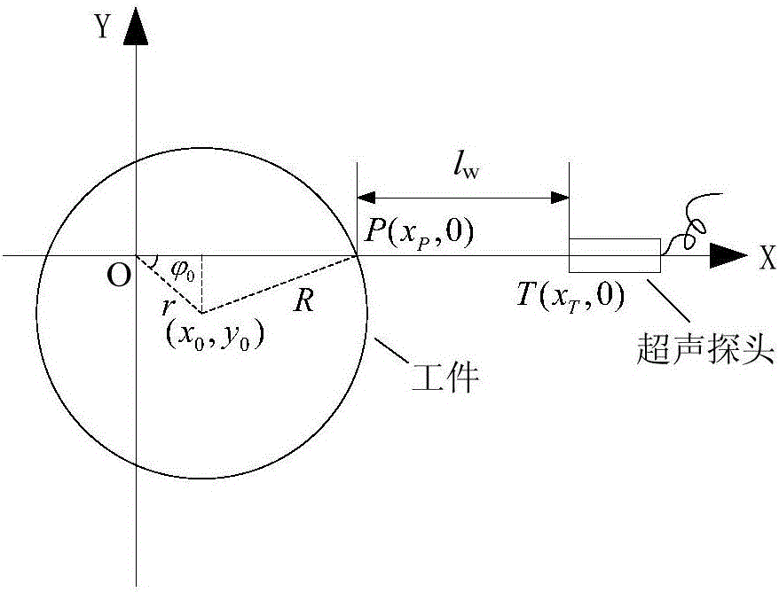
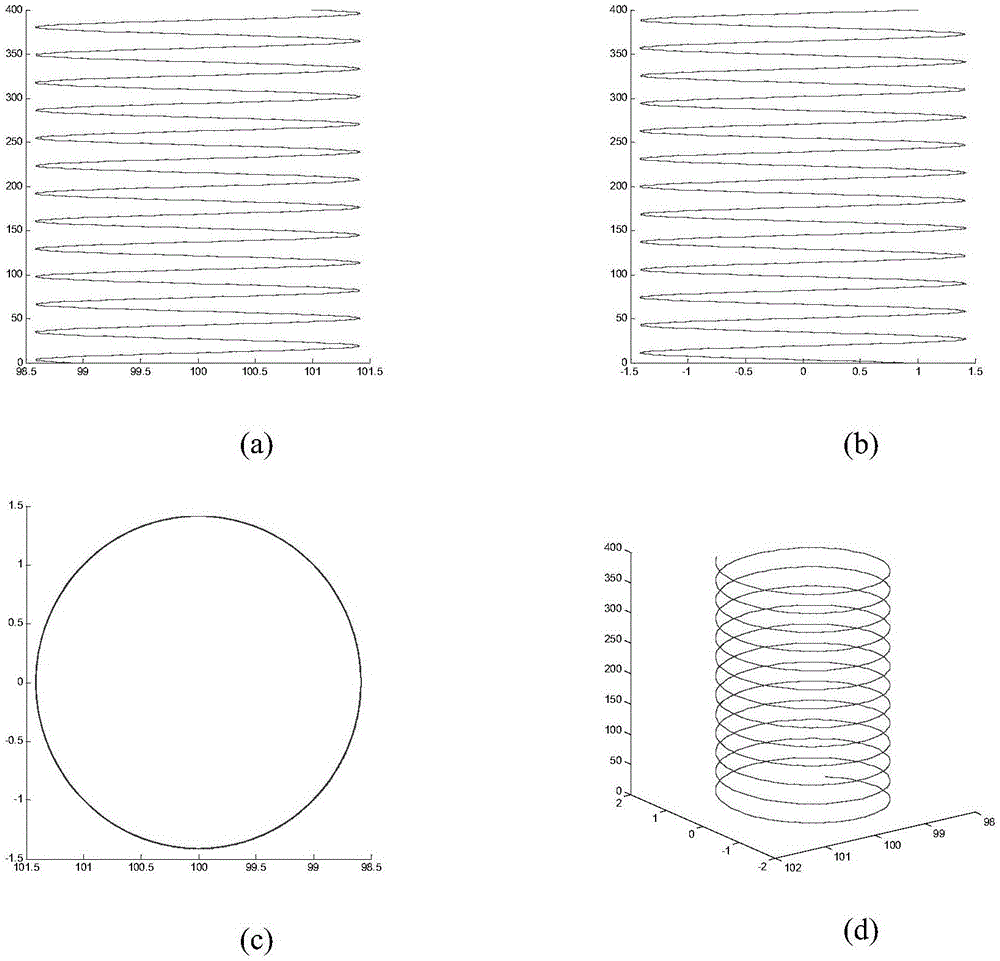
[0048] This specific embodiment takes the scanning of a cylindrical workpiece as an example. The present invention first fixes the tubular workpiece in a water tank filled with water, uses an ultrasonic pulse generator / receiver (also known as an ultrasonic instrument) to excite the ultrasonic longitudinal wave probe, and passes the ultrasonic longitudinal wave probe through The probe frame is clamped on the 7-DOF water immersion ultrasonic testing motion platform based on the Stäubli TX60L manipulator, and the movement of the motion platform is controlled by connecting the control circuit with the motion control card installed on the computer to adjust the position and posture of the ultrasonic longitudinal wav...


PUM


Abstract

The invention discloses a method for correcting and compensating ultrasonic C scanning paths under the circumstance that eccentric clamping between the center of a rotation body workpiece and a turnplate rotating shaft occurs when the ultrasonic longitudinal wave vertical incidence rotation body workpiece is adopted to detect inside defects. The method includes: detecting actual deviation of the workpiece through a fixed ultrasonic probe; calculating a path transformation matrix from a workpiece coordinate system to a world coordinate system; subjecting a scanning target path of the workpiece under the workpiece coordinate system to matrix transformation calculation to acquire moving paths of the probe under the world coordinate system.

Description

technical field [0001] The invention relates to an ultrasonic C-scanning path correction method considering workpiece eccentric clamping error Background technique [0002] Ultrasonic testing is a widely used non-destructive testing method, in which the ultrasonic C-scanning with longitudinal wave vertical incidence scans according to a certain path according to the shape of the measured object by placing the ultrasonic probe in the water, which can quickly, effectively and intuitively detect The defect image of a certain depth inside the measured object can be obtained, so it has become a commonly used method for detecting internal defects in parts and components in industry. [0003] When ultrasonic C-scanning is used to detect rotary parts, the workpiece is usually clamped by a turntable, the probe is held by a three-coordinate motion machine or a manipulator, and the composite motion path of the turntable, three-coordinate motion machine and manipulator is used for scann...

Claims


Application Information

Patent Timeline
IPC IPC(8): G01N29/26G01N29/265G01N29/27G01N29/30
CPCG01N29/26G01N29/265G01N29/27G01N29/30G01N2291/023
Inventor 李雄兵王炫润倪培君张荣繁宋永峰
Owner CENT SOUTH UNIV
Learn More