Fault location system and method for three-terminal transmission line

A line fault and ranging system technology, applied in the direction of detecting faults, fault locations, and measuring electricity according to conductor types, can solve the problems of weak reflected wave energy, increase the cost of fault location, and difficult detection, and achieve no measurement dead. The effect of reducing the area, reducing the quantity and reducing the cost

Inactive Publication Date: 2017-01-04
SICHUAN ZHONGGUANG LIGHTNING PROTECTION TECH
View PDF9 Cites 12 Cited by
  • Summary
  • Abstract
  • Description
  • Claims
  • Application Information

AI Technical Summary

Problems solved by technology

However, this method installs too many detection devices, which increases the cost of fault location....

Method used


Image

  • Fault location system and method for three-terminal transmission line
  • Fault location system and method for three-terminal transmission line
  • Fault location system and method for three-terminal transmission line

Examples


Embodiment Construction

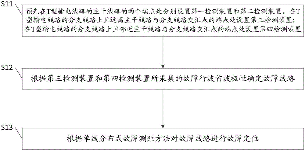
[0030] The core of the present invention is to provide a T-type line fault distance measurement system and method, which can reduce the cost of T-type line fault distance measurement and can locate the fault point more simply and accurately.

[0031] In order to make the above objects, features and advantages of the present invention more comprehensible, the specific implementation manners of the present invention will be described in detail below in conjunction with the accompanying drawings.

[0032] In the following description, specific details are set forth in order to provide a thorough understanding of the present invention. However, the present invention can be implemented in many other ways than those described here, and those skilled in the art can make similar extensions without departing from the connotation of the present invention. Accordingly, the present invention is not limited to the specific embodiments disclosed below.

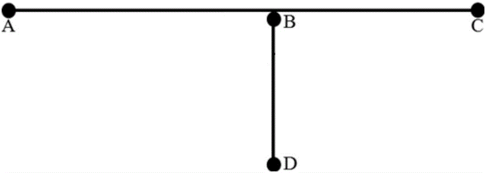
[0033] Please refer to figure 1 , ...


PUM


Abstract

The invention discloses a fault location system for a three-terminal transmission line. The fault location system comprises a first detecting device, a second detecting device, a third detecting device, a fourth detecting device and a treatment device, wherein the first detecting device and the second detecting device are located at two endpoints of the main line of the three-terminal transmission line; the third detecting device is arranged at the endpoint, away from the intersection of the main line and a branch line, on the branch line of the three-terminal transmission line; the fourth detecting device is arranged at the end point, close to the intersection of the main line and the branch line, on the branch line of the three-terminal transmission line; the treatment device is in communication connection with the detecting devices and used for determining the faulty line of the head wave polarity of fault traveling waves collected by the third detecting device and the fourth detecting device and performing fault location according to a single line distribution type fault location method. The fault location system has the advantages that the number of the detecting devices is reduced, fault location cost is lowered, reflection wave information needs not to be used, location reliability is increased, and measuring dead zones are avoided. Correspondingly, the invention further provides a fault location method for the three-terminal transmission line, and the effects of the fault location system and the fault location method are identical.

Description

technical field [0001] The invention relates to the field of intelligent diagnosis of power transmission systems, in particular to a T-type line fault ranging system and method. Background technique [0002] With the rapid development of the power network, the application of T-shaped transmission lines is becoming more and more extensive. However, due to the strong power transmission capacity and heavy load of the T-shaped line, once a failure occurs, it may cause more serious consequences than conventional transmission lines. [0003] However, the fault location method of T-type lines is relatively lagging behind that of conventional lines. At present, the commonly used fault location method for T-shaped lines is to install at least two sets of detection devices on each branch line of the T-shaped line, use the energy of the first wave to judge the fault branch, and use the fault traveling wave received by the detection device on the fault branch Further determine the fau...

Claims


Application Information

Patent Timeline
IPC IPC(8): G01R31/08
CPCG01R31/085G01R31/088
Inventor 李杰孙铭江赖军龚玲杨国华
Owner SICHUAN ZHONGGUANG LIGHTNING PROTECTION TECH
Why Eureka
Try Eureka