Light adjusting structure of display device, backlight module and display device
A technology of a display device and a backlight module, which is applied in the field of display and can solve problems such as the inability of a light guide plate to control the brightness of image display
- Summary
- Abstract
- Description
- Claims
- Application Information
AI Technical Summary
Problems solved by technology
Method used
Image

Examples
Embodiment 1
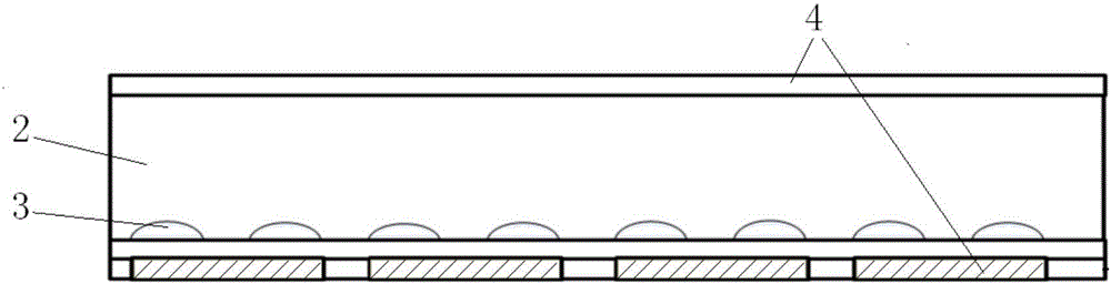
[0034] This embodiment provides a dimming structure of a display device, such as figure 2 As shown, it includes: a light guide plate 2, the light-emitting surface of the light guide plate 2 is the first surface, and the surface opposite to the first surface is the second surface; The mesh point 3, the material of the scattering mesh point 3 includes electrorefractive material; the electric field control unit 4 is used to change the electric field at the location of the scattering mesh point 3 so that the scattering mesh point 3 changes the refractive index.
[0035] In the light-adjusting structure of this embodiment, the electric field at the location of the scattering network point 3 is changed by the electric field control unit 4 to change the refractive index of the scattering network point 3, so that the optical properties of the electro-refractive index material are changed, and the total reflection of the light guide plate 2 is realized. , that is, there is no outgoing...
Embodiment 2
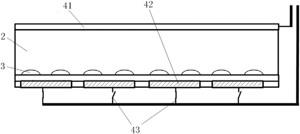
[0037] This embodiment provides a dimming structure of a display device, such as image 3 As shown, it includes: a light guide plate 2; a scattering grid point 3 that is arranged on the second surface of the light guide plate 2 and protrudes to the first surface, and the material of the scattering grid point 3 includes an electro-refractive material; and is used to change the position of the scattering grid point 3 The electric field control unit 4 of the electric field at the place, wherein the electric field control unit 4 includes: a transparent conductive layer 41 arranged on the first surface of the light guide plate 2; a dimming substrate 42 arranged on the second surface of the light guide plate 2; a controller 43, It is used to control the voltage between the dimming substrate 42 and the transparent conductive layer 41 .
[0038] Wherein, the transparent conductive layer 41 and the dimming substrate 42 are disposed on the upper and lower surfaces of the light guide pla...
Embodiment 3
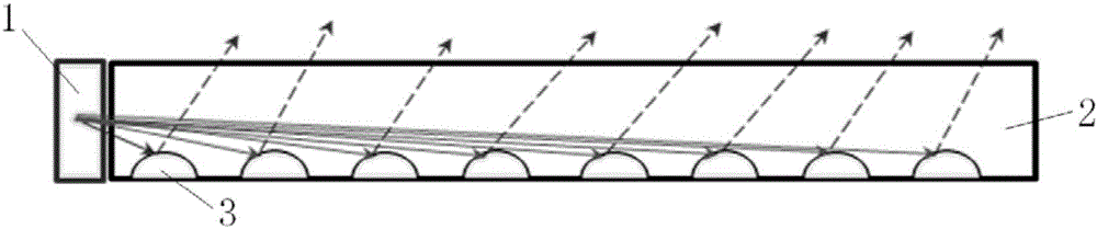
[0046] This embodiment provides a backlight module, including the above-mentioned dimming structure and a light source 1 located at the side of the light guide plate 2 of the dimming structure.
[0047] Preferably, the controller 43 controls the voltage between the dimming substrate 42 and the transparent conductive layer 41 to be 0, the refractive index of the scattering dots 3 is 1.468, and the light emitted by the light source 1 is totally reflected in the light guide plate 2 .
[0048] Preferably, a reflective sheet 5 is provided between the light guide plate 2 and the dimming substrate 42; the refractive index of the scattering dots 3 is greater than 1.5, and the controller 43 controls the voltage V between the dimming substrate 42 and the transparent conductive layer 41 to be greater than or equal to 0.32h / a , the light emitted by the light source 1 is refracted at the scattering dots 3, diffusely reflected by the reflective sheet 5, and emitted from the first surface.
...
PUM
| Property | Measurement | Unit |
|---|---|---|
| thickness | aaaaa | aaaaa |
| refractive index | aaaaa | aaaaa |
| refractive index | aaaaa | aaaaa |
Abstract
Description
Claims
Application Information
 - R&D
- Intellectual Property
- Life Sciences
- Materials
- Tech Scout
- Unparalleled Data Quality
- Higher Quality Content
- 60% Fewer Hallucinations
Browse by: Latest US Patents, China's latest patents, Technical Efficacy Thesaurus, Application Domain, Technology Topic, Popular Technical Reports.
© 2025 PatSnap. All rights reserved.Legal|Privacy policy|Modern Slavery Act Transparency Statement|Sitemap|About US| Contact US: help@patsnap.com