Electronic equipment antenna main reflector and preparation method thereof

A technology of electronic equipment and main reflector, applied in antennas, chemical instruments and methods, electrical components, etc., can solve the problems of poor antenna surface strength and poor reflection effect of the main reflector, and achieve good adhesion and easy processing technology. Precise, impact-enhancing effects

Active Publication Date: 2019-01-22
深圳市华讯方舟光电技术有限公司 +1
View PDF10 Cites 0 Cited by
  • Summary
  • Abstract
  • Description
  • Claims
  • Application Information

AI Technical Summary

Problems solved by technology

[0004] The first purpose of the present invention is to provide a main reflective surface of an electronic equipment antenna to solve the technical problems of poor reflection effect of the main reflective surface and poor strength of the antenna surface
[0005] The second object of the present invention is to provide a method for preparing the main reflector of the antenna of an electronic device, so as to solve the technical problems of poor reflection effect of the main reflector and poor strength of the antenna surface

Method used


Image

  • Electronic equipment antenna main reflector and preparation method thereof
  • Electronic equipment antenna main reflector and preparation method thereof

Examples


Embodiment Construction

[0029] The embodiments of the present invention will be described in detail below in conjunction with the examples. If no specific conditions are indicated in the examples, it will be carried out according to the conventional conditions or the conditions suggested by the manufacturer.

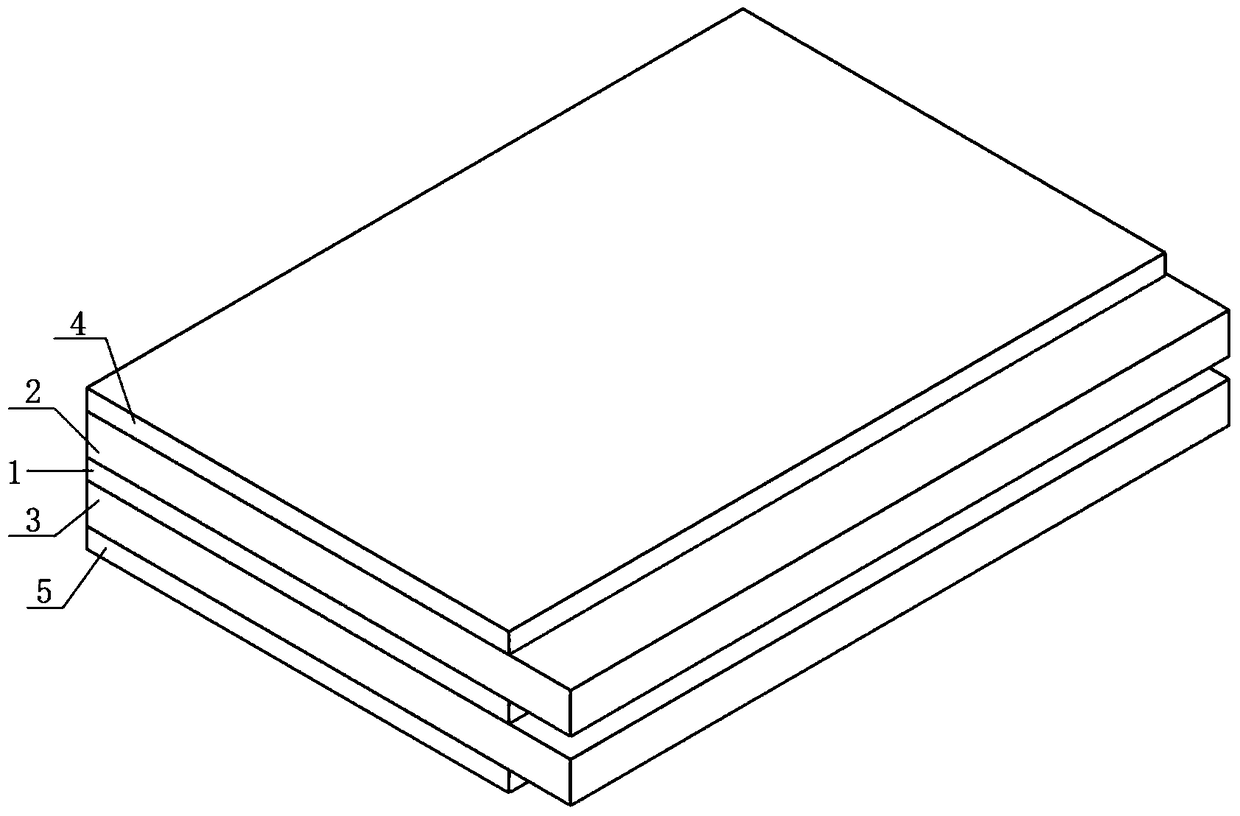
[0030] figure 1 The electronic equipment antenna main reflecting surface of an embodiment of the present invention is shown, which includes:

[0031] Aluminum foil cloth layer 1;

[0032] The first glass fiber cloth layer 2, the first glass fiber cloth layer 2 is bonded to one side of the plain weave aluminum foil cloth layer 1 with hot melt adhesive;

[0033] The second glass fiber cloth layer 3, the second glass fiber cloth layer 3 is bonded to the other side of the plain weave aluminum foil cloth layer 1 with hot melt adhesive;

[0034] The first unsaturated resin impregnated layer 4, the first unsaturated resin impregnated layer 4 is obtained by impregnating glass fiber cloth in the unsat...


PUM

PropertyMeasurementUnit
thicknessaaaaaaaaaa
thicknessaaaaaaaaaa

Abstract

The invention discloses an electronic device antenna main reflection surface and a preparation method. The electronic device antenna main reflection surface comprises an aluminum foil layer, a first glass fiber cloth layer, a second glass fiber cloth layer, a first nonsaturated resin glue dipping layer, and a second nonsaturated resin glue dipping layer. The first glass fiber cloth layer is adhered on one side of the tabby aluminum foil cloth layer through a hot melt glue; the second glass fiber cloth layer is adhered on the other side of the tabby aluminum foil layer through the hot melt glue; the first nonsaturated resin glue dipping layer is connected to the first glass fiber cloth layer through lamination; and the second nonsaturated resin glue dipping layer is connected to the second glass fiber cloth layer through lamination. The invention adopts the lamination molding technology and takes place of the metal mesh with the aluminum foil glass fiber. The aluminum foil fiber cloth forms the full reflection on the electromagnetic wave, and the adhesiveness between the aluminum foil glass fiber cloth and the resin is good, which enhances the stroke resistance of the antenna surface.

Description

technical field [0001] The invention belongs to the technical field of electronic equipment antennas, and in particular relates to a main reflection surface of an electronic equipment antenna and a preparation method of the above reflection surface. Background technique [0002] The satellite communication antenna has two functions: one function is to reflect the microwave signal from the communication satellite to the feed source and high frequency head at the focal point to complete the signal receiving function; the other function is to transmit the radio frequency signal transmitted by the high power amplifier of the earth station The signal is electromagnetically transformed into a microwave signal propagated in free space, and transmitted to the designated satellite to complete the launching function. The main indicators to measure satellite communication antennas are transceiver gain, transceiver efficiency, noise temperature, and radiation characteristics. The manufa...

Claims


Application Information

Patent Timeline
Patent Type & Authority Patents(China)
IPC IPC(8): H01Q15/14B32B15/14B32B17/02B32B17/04
Inventor 刘武丰
Owner 深圳市华讯方舟光电技术有限公司
Why Eureka
Try Eureka