
Special tools for laying out and installing cables for road power supply in cities or towns

A technology of cable layout and special tools, applied in the direction of cable laying equipment, etc., can solve the problems of cable wear, difficulty of adjustment, high labor intensity, etc., and achieve the effects of avoiding damage, reducing installation cycle, and reducing labor intensity

Inactive Publication Date: 2017-10-24
SHANGHE COUNTY POWER SUPPLY CO STATE GRID SHANDONG ELECTRIC POWER CO +1
View PDF8 Cites 0 Cited by
  • Summary
  • Abstract
  • Description
  • Claims
  • Application Information

AI Technical Summary

Problems solved by technology

[0002] Outdoor cable layout and installation is a relatively heavy and time-consuming work
In the prior art, when installing cables on roads in cities or towns, it is necessary to first set up electric poles or electric towers, then manually climb onto a electric pole and pull the cable to the top of the electric pole for fixing. For installation, other workers are required to cooperate with lifting and pulling the cable on the ground to adjust the position, and the labor intensity is relatively high.
In addition, after fixing a utility pole, it is necessary to climb to another utility pole and pull the cable to the top of the utility pole for fixed installation. The installation angle of the cable is completely adjusted by manual pulling, and the installation cycle Long, low installation efficiency
There are still several problems in the purely manual adjustment of the cable. When encountering uneven roads, the adjustment difficulty is greatly increased, and manual pulling adjustment is easy to cause wear and tear on the cable.

Method used


Image

  • Special tools for laying out and installing cables for road power supply in cities or towns
  • Special tools for laying out and installing cables for road power supply in cities or towns
  • Special tools for laying out and installing cables for road power supply in cities or towns

Examples


Embodiment Construction

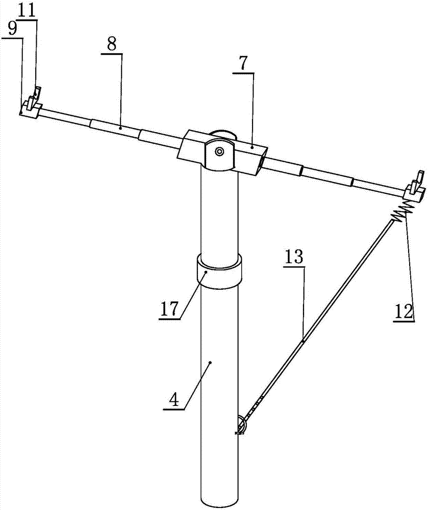
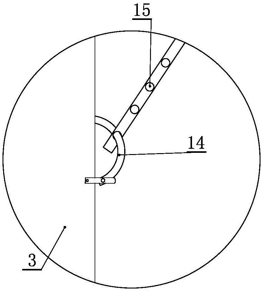
[0019] The following is attached Figure 1-5 The features and principles of the present invention are described in detail, and the examples given are only used to explain the present invention, not to limit the protection scope of the present invention.

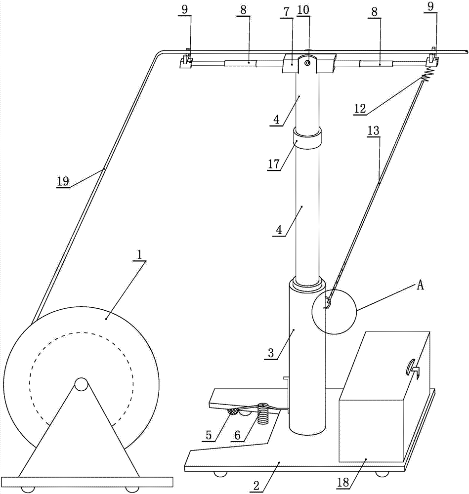
[0020] Such as figure 1 As shown, the invention includes a cable reel 1, a base 2, a lifting part and a cable supporting part. Wherein, the bottom of the lifting part is fixedly arranged at the center position of the upper surface of the base, and the bottom of the base is provided with universal wheels. In order to prevent the base from moving arbitrarily, a wheel lock can be added on the universal wheels.

[0021] The lifting part includes a lifting column 3 and a lifting arm 4, and the lifting part is provided with a hydraulic jacking assembly, which can be driven by a commonly used hydraulic cylinder. There is a pedal 5 on one side of the lifting column, and the bottom of the pedal is connected to the spring 6. The step...


PUM


Abstract

The invention discloses a special tool for arrangement and installation of a cable for power supply in an urban or rural road. The special tool comprises a cable winding wheel, a base, a lifting part and a cable supporting part, and also comprises an adjustment part, wherein the cable winding wheel is used for realizing wire winding for the cable supporting part; the lifting part is used for jacking the cable supporting part through a hydraulic cylinder and auxiliaries for realizing height adjustment; the cable supporting part is fixed on the top of the lifting part with adjustable length and used for supporting the cable; the adjustment part can be used for adjusting the installation angle of the cable; and a lifting arm is divided into an upper part and a lower part which are connected through a diversion connector, so that the adjustment of the cable in the horizontal plane within any one angle can be realized. By adoption of the special tool, automatic wire releasing can be realized; the cable is not required to be placed on the ground to be manually dragged, thereby greatly lowering labor intensity in installation, shortening the installation period, and avoiding damage to the cable in an installation process.

Description

technical field [0001] The invention relates to the technical field of cable arrangement and installation equipment for outdoor power supply, in particular to a special tool for cable arrangement and installation for road power supply in cities or towns. Background technique [0002] The layout and installation of outdoor cables is a relatively arduous and time-consuming task. In the prior art, when installing cables on roads in cities or towns, it is necessary to first set up electric poles or electric towers, then manually climb onto a electric pole and pull the cable to the top of the electric pole for fixing. For installation, at this time, other staff members are required to cooperate with lifting and pulling the cables on the ground to adjust the position, and the labor intensity is relatively large. In addition, after fixing a utility pole, it is necessary to climb to another utility pole and pull the cable to the top of the utility pole for fixed installation. The i...

Claims


Application Information

Patent Timeline
Patent Type & Authority Patents(China)
IPC IPC(8): H02G1/06
CPCH02G1/06
Inventor 王焱王琳张璐璐
Owner SHANGHE COUNTY POWER SUPPLY CO STATE GRID SHANDONG ELECTRIC POWER CO
Learn More