
Anchoring, lining and guniting all-in-one machine

An all-in-one machine and lining technology, applied in wellbore lining, tunnel lining, bolt installation, etc., can solve the problems of poor equipment coordination, low safety guarantee, complicated construction process, etc., to achieve good explosion-proof ability, high construction efficiency, The effect of convenient construction

Pending Publication Date: 2021-12-31
陕西旬邑青岗坪矿业有限公司 +1
View PDF0 Cites 0 Cited by
  • Summary
  • Abstract
  • Description
  • Claims
  • Application Information

AI Technical Summary

Problems solved by technology

[0002] Existing tunnel construction methods include the new Austrian method, first drilling and blasting, followed by bolting and spraying support, and then concrete support; or using the submersion method, when the tunnel pipe section sinks to the bottom, it is connected and sealed to form a tunnel; the shield tunneling method is to excavate Machines are used as shields for excavation; in the prior art, the support of tunnels or roadways is mostly constructed by manual means, and manual construction requires multiple mechanical equipment, lack of cooperation between equipment, and poor equipment coordination effect, resulting in poor construction efficiency. low problem
[0003] In order to build a smart mine and realize automatic tunnel excavation construction, it is necessary to further improve the existing support methods. Usually, the construction of the roadway requires multiple steps such as measurement. The construction process is complicated, and the tunnel and the roadway with a long service life Lining and shotcrete support are also required. The construction speed of this kind of construction is slow, and the safety guarantee level of personnel construction is low. For this reason, it is necessary to further improve the existing construction equipment and construction methods

Method used


Image

  • Anchoring, lining and guniting all-in-one machine
  • Anchoring, lining and guniting all-in-one machine
  • Anchoring, lining and guniting all-in-one machine

Examples


Embodiment Construction

[0024] The specific embodiments of the present invention will be described in detail below in conjunction with the accompanying drawings, but it should be understood that the protection scope of the present invention is not limited by the specific embodiments.

[0025] Unless expressly stated otherwise, throughout the specification and claims, the term "comprise" or variations thereof such as "includes" or "includes" and the like will be understood to include the stated elements or constituents, and not Other elements or other components are not excluded.

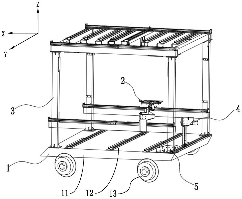
[0026] Such as figure 1 As shown, according to a preferred embodiment of the present invention, an anchoring lining and spraying machine for tunnel or roadway construction mainly includes a traveling mechanism 1, a bolt anchoring mechanism 2, a brick lining mechanism 3, a concrete spraying mechanism 4 and Monitoring and control system 5 and other main components.

[0027] see figure 1 , in some embodiments, the walking m...


PUM


Abstract

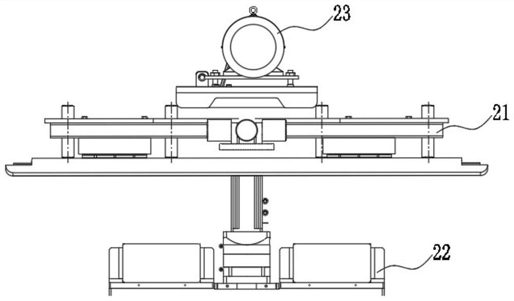
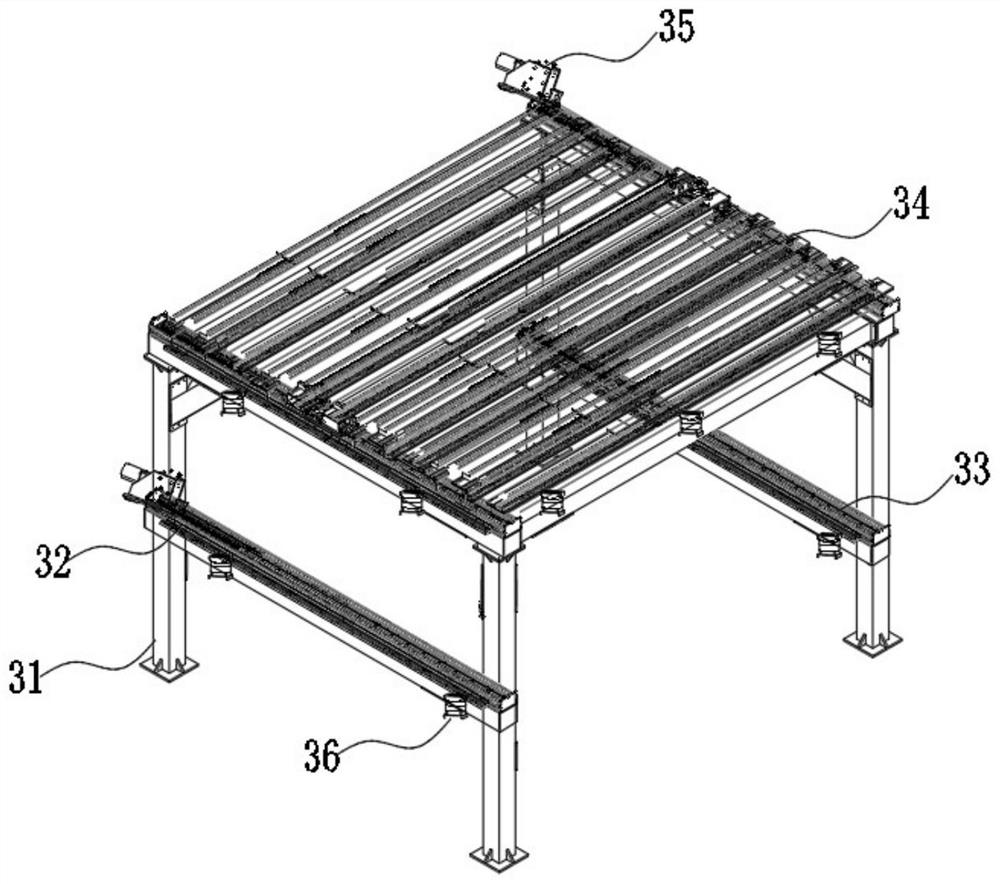
The invention discloses an anchoring, lining and guniting all-in-one machine. The anchoring, lining and guniting all-in-one machine comprises a walking mechanism, an anchor rod anchoring mechanism, a brick lining mechanism and a concrete guniting mechanism; a positioning rack is arranged on a bottom frame and can move front and back or left and right on the bottom frame along the horizontal plane; a bench drilling machine and an anchoring machine can move up and down in the vertical direction on the positioning rack, rotate in the horizontal plane and rotate in the vertical plane; the brick lining mechanism comprises a left lifting frame, a right lifting frame and a top plate lifting frame; the left lifting frame and the right lifting frame can move up and down along the two sides of a supporting frame; the top plate lifting frame can move up and down in the vertical direction with the supporting frame as the basis; the concrete guniting mechanism comprises a movable base and a guniting machine; the movable base can move up and down and left and right along the rear plane of the supporting frame; and the guniting machine can rotate on the movable base along the rear plane of the supporting frame. Thus, automatic supporting design and construction of roadways or tunnels can be achieved.

Description

technical field [0001] The invention relates to the technical field of civil engineering, in particular to an anchoring lining and spraying grouting integrated machine used for tunnel or roadway construction. Background technique [0002] Existing tunnel construction methods include the new Austrian method, first drilling and blasting, followed by bolting and spraying support, and then concrete support; or using the submersion method to establish tunnel pipes that are connected and sealed when they sink to the bottom to form a tunnel; the shield tunneling method is to excavate Machines are used as shields for excavation; in the prior art, the support of tunnels or roadways is mostly constructed by manual means, and manual construction requires multiple mechanical equipment, lack of cooperation between equipment, and poor equipment coordination effect, resulting in poor construction efficiency. low problem. [0003] In order to build a smart mine and realize automatic tunnel...

Claims


Application Information

Patent Timeline
Patent Type & Authority Applications(China)
IPC IPC(8): E21D11/00E21D20/00E21B7/02E21D11/06E21D11/10
CPCE21D11/00E21D20/003E21B7/02E21D11/06E21D11/10E21D11/105
Inventor 张笃学彭培柱邹艳艳沈海洋孙大勇周琨汪峰刘春峰肖超沈海浪李聪
Owner 陕西旬邑青岗坪矿业有限公司
Learn More