Building shock insulation ditch cover plate structure

A ditch cover and seismic isolation technology, which is applied in construction, infrastructure engineering, protection devices, etc., can solve problems such as misunderstanding of design, inability to move freely, and limited use of span, so as to achieve simple installation and construction and improve construction accuracy , Improve the effect of isolation efficiency

Active Publication Date: 2014-05-14
CHINA AVIATION PLANNING & DESIGN INST GRP
View PDF7 Cites 16 Cited by
  • Summary
  • Abstract
  • Description
  • Claims
  • Application Information

AI Technical Summary

Problems solved by technology

[0004] (1) The rigidity and bearing capacity of the cantilever type seismic isolation ditch cover are small, and the use span is limited;
[0005] (2) The gap of the isolation joint is very small, and the construction accuracy is difficult to control, and the construction error will easily cause the gap between the isolation ditch cover plate and the isolation ditch retaining wall to be unable to move freely, resulting in the isolation of the isolation structure when an earthquake occurs. Efficiency is greatly limited, and even damage
[0006] (3) Under normal circumstances, the cover plate of the seismic isolation ditch is constructed together with the loose water of the building. The construction personnel have misunderstood the design or the construction process cannot attract the attention of the construction personnel, which may easily lead to misalignment between the cover plate of the seismic isolation ditch and the retaining wall. Poured as one, can not move relative to each other;
[0007] (4) Once the cantilevered seismic isolation ditch cover is damaged, it is difficult to repair

Method used


Image

  • Building shock insulation ditch cover plate structure
  • Building shock insulation ditch cover plate structure
  • Building shock insulation ditch cover plate structure

Examples


Embodiment Construction

[0024] Preferred embodiments of the present invention will be described in detail below in conjunction with the accompanying drawings.

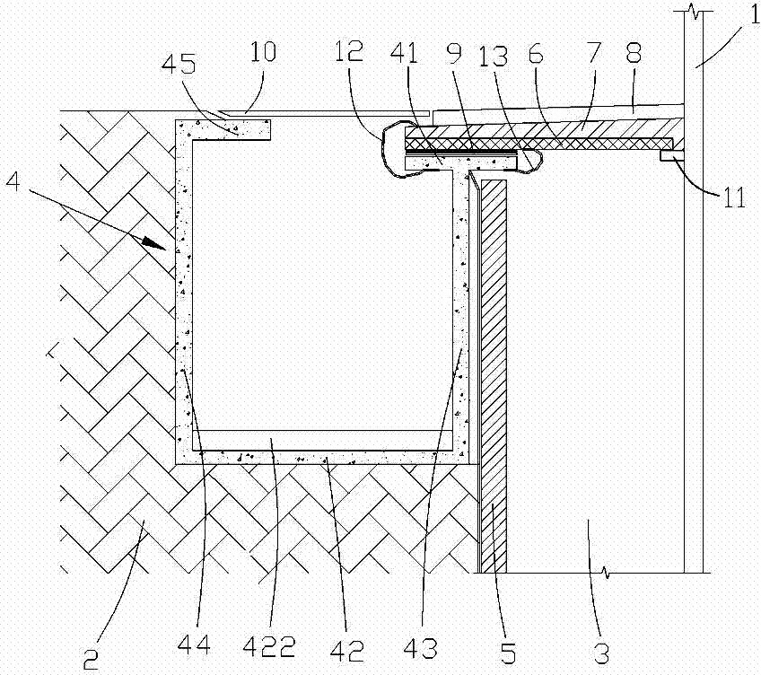
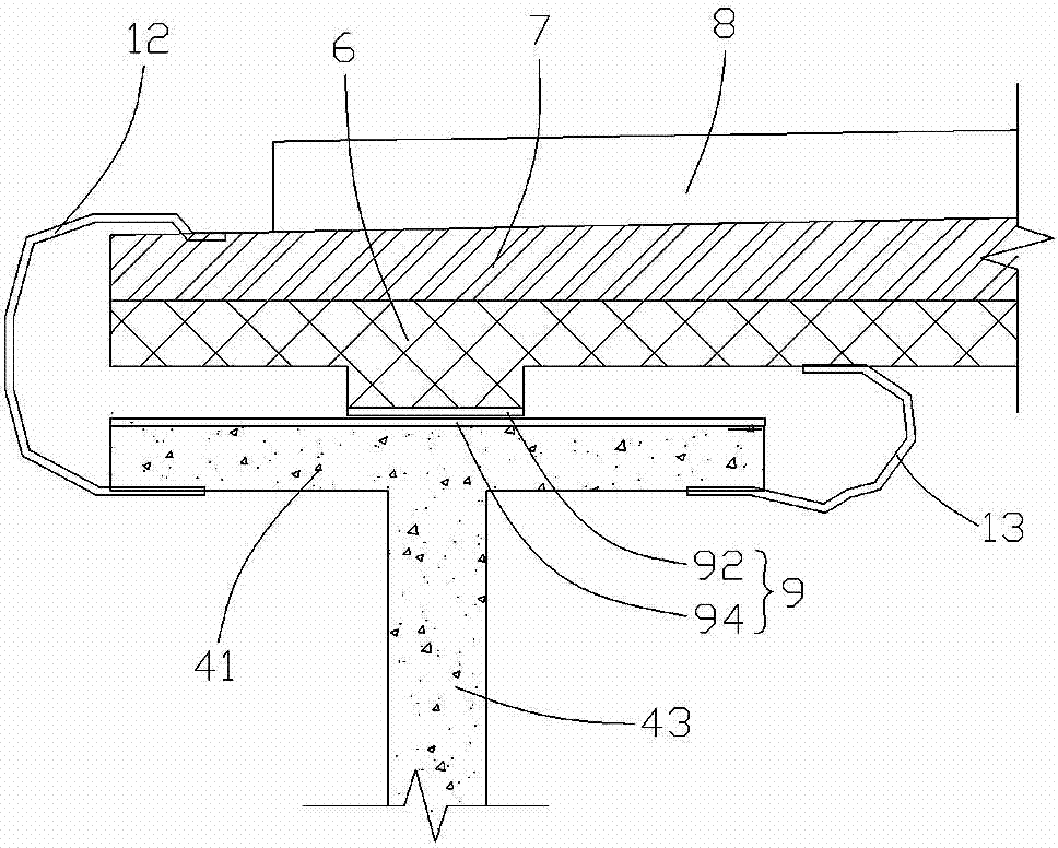
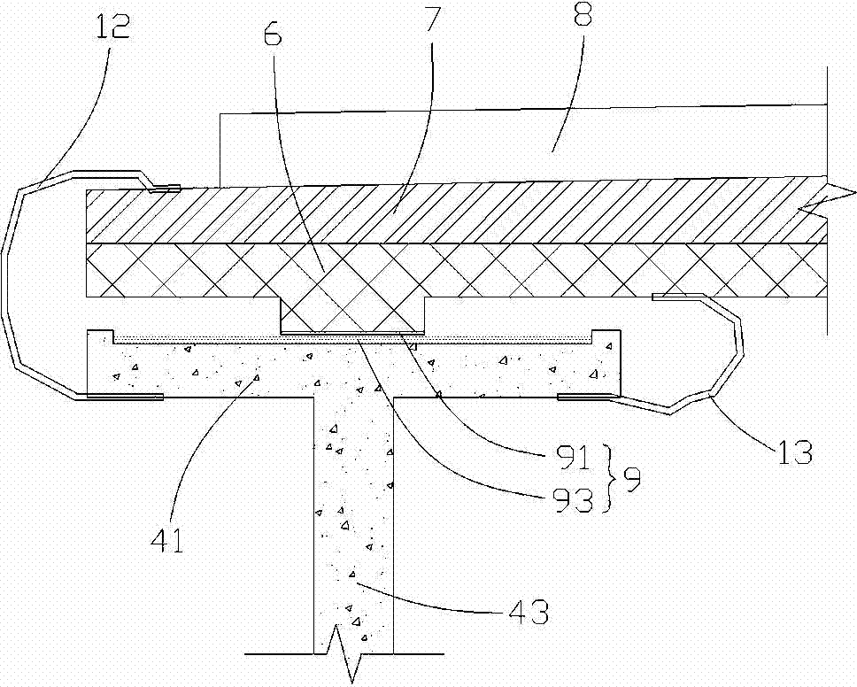
[0025] see Figure 1 to Figure 3 , The structure of the building isolation ditch cover plate structure of the present invention includes an isolation ditch 3 between the main body of the isolation building 1 and the site soil 2, a drainage member 4 located in the site soil 2, and a drainage member 4 located in the isolation structure. The seismic isolation ditch retaining wall 5 in the seismic ditch 3, the end of the drainage member 4 close to the seismic isolation ditch 3 is provided with a support plate 41, and a prefabricated cover is connected between the support plate 41 and the main body 1 of the seismic isolation building plate 6 and the cast-in-place laminated layer 7 arranged on the prefabricated cover plate 6, the prefabricated cover plate 6 and the cast-in-place laminated layer 7 are fixedly connected to the main body 1 of the eart...


PUM


Abstract

The invention provides a building shock insulation ditch cover plate structure. The building shock insulation ditch cover plate structure comprises a shock insulation ditch arranged between a shock insulation building body and a field soil body, a water draining component arranged in the field soil body and a shock insulation ditch retaining wall arranged in the shock insulation ditch. A supporting plate is arranged at the end, close to the shock insulation ditch, of the water draining component, a prefabricated cover plate and a cast-in-place laminated layer arranged on the prefabricated cover plate are connected between the supporting plate and the shock insulation building body, both the prefabricated cover plate and the cast-in-place laminated layer are fixedly connected to the shock insulation building body, and a sliding layer is arranged between the prefabricated cover plate and the supporting plate so that the prefabricated cover plate and the shock insulation ditch retaining wall can move more relatively freely under the effects of earthquakes. The building shock insulation ditch cover plate structure is simple in installation and construction, reduces false operations of construction personnel, improves the construction precision and guarantees the fact that the shock insulation building body and a space enclosing structure around can slide freely, and the shock insulation efficiency of the shock insulation structure is improved.

Description

technical field [0001] The invention relates to the technical field of building shock isolation, in particular to a structure of a building shock isolation ditch cover plate. Background technique [0002] Earthquake is a natural disaster, and the disasters caused by it have caused huge disasters to human beings. The traditional anti-seismic method of building design adopts "hard resistance" methods such as strengthening the structure, increasing the cross-sectional size of components, increasing component reinforcement, and increasing structural rigidity to resist earthquakes. However, due to the randomness of earthquakes, the magnitude of earthquakes is uncertain. Using the traditional "hard resistance" seismic method to design according to the actual intensity of the performance goals of the building structure's own safety and personnel safety may not be guaranteed, and it is even more difficult to control the secondary disasters caused by earthquakes and achieve the goal ...

Claims


Application Information

Patent Timeline
Patent Type & Authority Applications(China)
IPC IPC(8): E02D31/08
Inventor 管志忠王明珠张玲张曼生葛家琪张国军刘鑫刚马伯涛张奇铭
Owner CHINA AVIATION PLANNING & DESIGN INST GRP
Why Eureka
Try Eureka