Device and method for in-situ remediation of fluoride-polluted soil

An in-situ remediation and contaminated soil technology, applied in the field of remediation of fluorine-contaminated soil, can solve the problems of high cost, practicability to be improved, and long time, and achieve the effects of easy construction and installation, improved remediation efficiency, and improved removal efficiency

Active Publication Date: 2019-08-30
HENAN UNIV OF SCI & TECH
View PDF12 Cites 9 Cited by
  • Summary
  • Abstract
  • Description
  • Claims
  • Application Information

AI Technical Summary

Problems solved by technology

The restoration is basically based on ex-situ restoration. The soil particles need to be broken, ex-situ leached, and phyto

Method used


Image

  • Device and method for in-situ remediation of fluoride-polluted soil
  • Device and method for in-situ remediation of fluoride-polluted soil
  • Device and method for in-situ remediation of fluoride-polluted soil

Examples


Embodiment 1

[0062] Fluorine flux is used in the production of electrolytic aluminum, so the surrounding farmland is easily polluted by fluorine. This plan selects a piece of polluted farmland of 1 square meter around the electrolytic aluminum plant as the implementation object.

[0063] First, the physical and chemical properties were analyzed, and the measured soil pH was 8.3, the soil organic matter content was 17.5 g / kg, and the soil cation exchange capacity was 19.9 cmol / kg. The total fluorine content in the soil was measured to be 1416.2 mg / kg, of which water-soluble fluorine accounted for 66.3%, exchangeable fluorine accounted for 7.3%, iron-oxygen-bound fluorine accounted for 3.9%, organic-bound fluorine accounted for 3.9%, and residual fluorine accounted for 18.6%. ;

[0064] After that, 0.1 mol / L fluorine eluent (0.1 mol / L ammonia solution, 0.1 mol / L sodium acetate solution, 0.1 mol / L hydroxylamine hydrochloride solution, 0.5% carboxymethyl chitosan Sugar solution, mixed accord...

Embodiment 2

[0070] In this embodiment, a polluted farmland of 1 square meter around an electrolytic aluminum plant is selected as the implementation object.

[0071] First, the physical and chemical properties were analyzed, and the measured soil pH was 8.2, the soil organic matter content was 17.2 g / kg, and the soil cation exchange capacity was 20.1 cmol / kg. The total fluorine content in the soil was measured to be 1425.7 mg / kg, of which water-soluble fluorine accounted for 65.1%, exchangeable fluorine accounted for 8.5%, iron-oxygen-bound fluorine accounted for 3.7%, organic-bound fluorine accounted for 3.8%, and residual fluorine accounted for 18.9%. %.

[0072] After that, 0.1 mol / L fluorine eluent (0.1 mol / L ammonia solution, 0.1 mol / L sodium acetate solution, 0.1 mol / L hydroxylamine hydrochloride solution, 0.5% carboxymethyl chitosan Sugar solution, mixed according to the volume ratio of 4:1:4:1) is sprayed on the surface of the polluted soil, and the surface polluted soil is turne...


PUM

PropertyMeasurementUnit
Diameteraaaaaaaaaa
Heightaaaaaaaaaa

Abstract

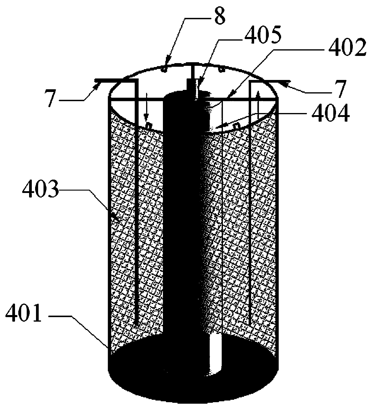
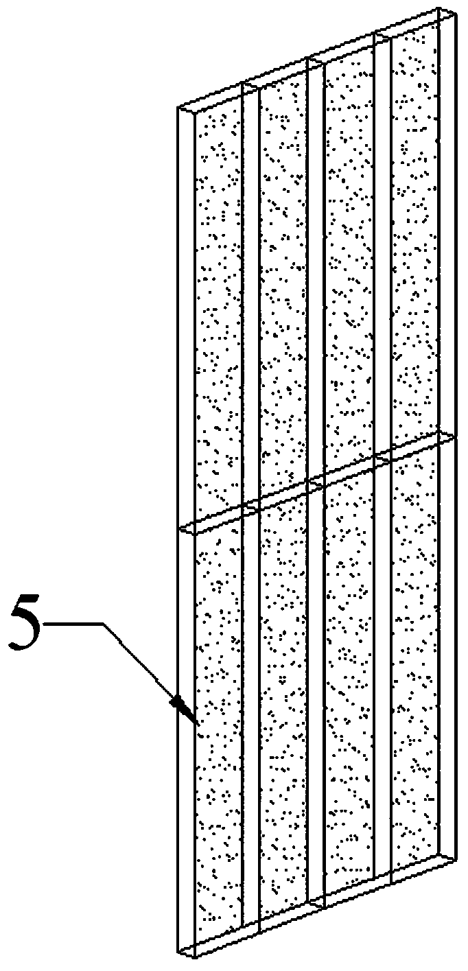
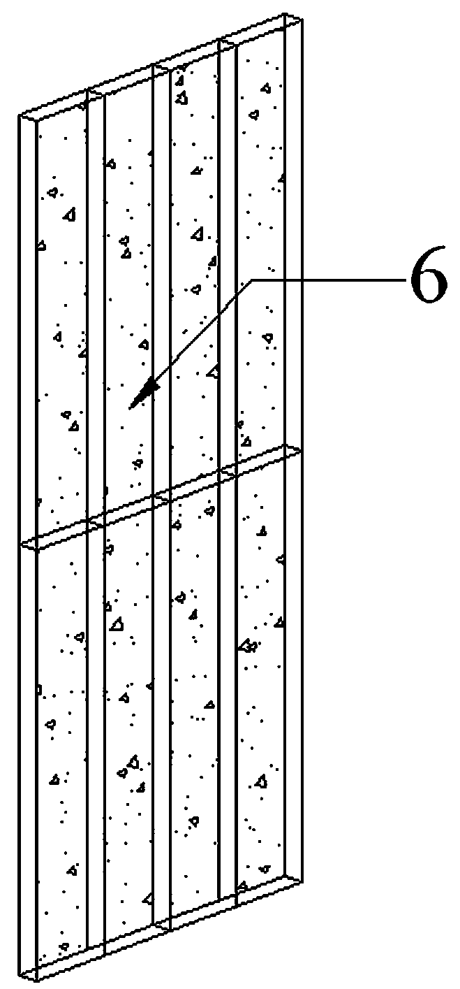
The invention discloses a device and method for in-situ remediation of fluoride-polluted soil, which can adopt a permeable reactive barrier in combination with an electrodynamics technology to performin-situ remediation on fluoride-polluted soil. The remediation method comprises the steps of performing physicochemical property measurement on soil, performing fluorine elution on the surface of thesoil using a soil eluent, laying an electrode capable of being repaired in situ, constructing an electrolyte continuous cycle loop between an electrolysis chamber and an electrolyte storage tank of the in situ electrode, and applying a direct-current electric field between the anode and cathode with a low-pressure pulsed power supply. Fluorinion carrying negative charge moves towards an anode chamber through electromigration under the action of the electric field and is adsorbed by a permeable reactive barrier in the anode chamber, meanwhile, fluorine, in the form of fluoride or other solubleions, moves towards a cathode chamber through electrodialysis and is adsorbed by a permeable reactive barrier in the cathode chamber, after the remediation is completed, the electrode is taken out, thereby completing the removal and remediation of fluorine pollutants in the soil.

Description

technical field [0001] The invention belongs to the technical field of restoration of fluorine-contaminated soil, and specifically relates to an in-situ permeable reaction grid combined with electrodynamic restoration method for fluorine-contaminated soil. [0002] technical background [0003] In recent years, with the rapid development of industry and agriculture and the increase of population, serious soil pollution has been caused, including soil fluorine pollution. For example, in agricultural production activities, long-term use of phosphate fertilizers and sewage irrigation will lead to soil fluorine pollution; in industrial production activities, fluorine-containing gases and dust produced Particles, through rainfall, leaching and other processes, allow fluorine to enter the soil, which will also cause fluorine pollution in the soil. Studies have shown that excessive fluorine intake is harmful to the human body and can lead to fluorosis. Endemic fluorosis, referred ...

Claims


Application Information

Patent Timeline
IPC IPC(8): B09C1/08
CPCB09C1/08B09C1/085B09C2101/00
Inventor 周鸣许景明朱书法马腾
Owner HENAN UNIV OF SCI & TECH
Why Eureka
Try Eureka