
Hydropower station set load distribution method for power grid multi-stage power transmission section

A technology of transmission section and distribution method, which is applied in the direction of circuit device, AC network circuit, single network parallel feeding arrangement, etc., and can solve the problem of low solution efficiency

Inactive Publication Date: 2017-01-04
HUAZHONG UNIV OF SCI & TECH
View PDF3 Cites 6 Cited by
  • Summary
  • Abstract
  • Description
  • Claims
  • Application Information

AI Technical Summary

Problems solved by technology

[0004] Aiming at the above defects or improvement needs of the prior art, the present invention provides a load distribution method for hydropower station units facing the multi-level power transmission section of the power grid. Its purpose is to transform the load distribution process from The discrete domain is transformed into a continuous domain, and the calculation efficiency is improved on the premise of meeting the accuracy requirements, so as to solve the technical problem of low efficiency in solving the load distribution of hydropower station units with multi-level transmission section feed-in

Method used


Image

  • Hydropower station set load distribution method for power grid multi-stage power transmission section
  • Hydropower station set load distribution method for power grid multi-stage power transmission section
  • Hydropower station set load distribution method for power grid multi-stage power transmission section

Examples


Embodiment Construction

[0061] In order to make the object, technical solution and advantages of the present invention clearer, the present invention will be further described in detail below in conjunction with the accompanying drawings and embodiments. It should be understood that the specific embodiments described here are only used to explain the present invention, not to limit the present invention. In addition, the technical features involved in the various embodiments of the present invention described below can be combined with each other as long as they do not constitute a conflict with each other.

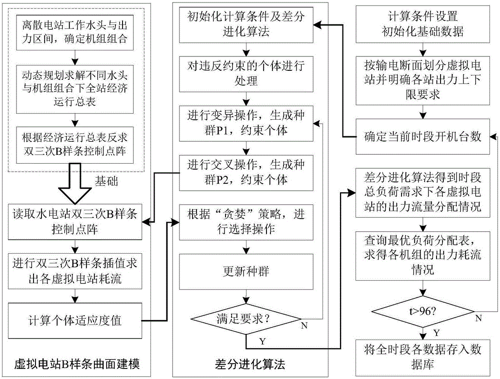
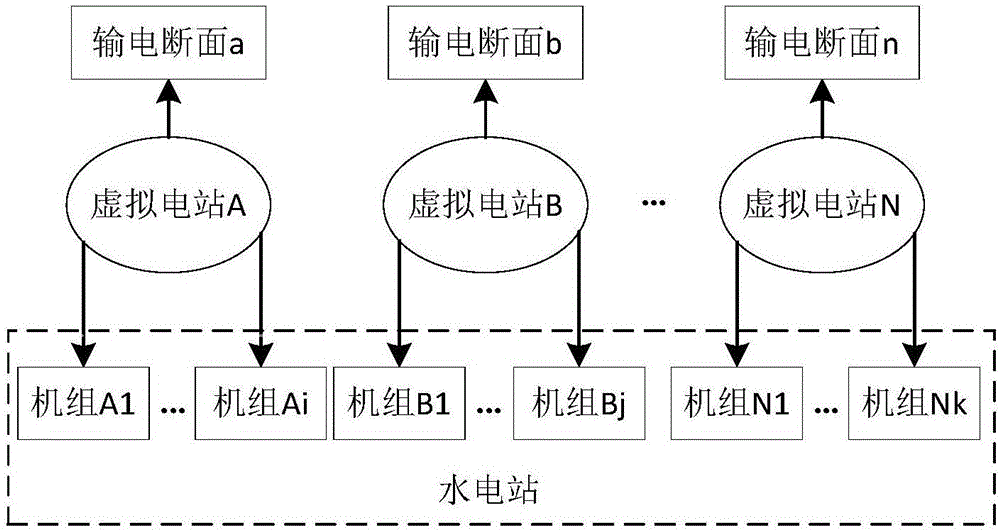
[0062] The load distribution method for hydropower generating units oriented to the multi-level transmission section of the power grid provided by the embodiment, taking Qingjiang Geheyan Hydropower Station as an example, based on the bicubic B-spline surface of the dynamic characteristics of the virtual hydropower station, realizes the real-time load distribution of hydroelectric generating unit...


PUM


Abstract

The invention discloses a hydropower station set load distribution method for a power grid multi-stage power transmission section. The hydropower station set load distribution method comprises the following steps of dividing sets with different hydropower station fed-in grid output limits into different virtual hydropower stations, according to discrete dynamic characteristics of the sets of the virtual hydropower stations, obtaining an economic operation summary table based on different working heads and unit combinations of each virtual hydropower station; using a bicubic B-spline interpolation method to construct a dynamic characteristic three-dimensional surface of each virtual hydropower station; by taking the minimum water consumption rate of the hydropower station as a goal, establishing a real-time load distribution model of the virtual hydropower station; via using a differential evolution algorithm in combination with the dynamic characteristic three-dimensional surface, solving the real-time load distribution model to obtain a load distributed by each virtual hydropower station; and obtaining optimal load distribution and flow consumption of each set of the virtual hydropower station based on the load and the economic operation summary table. The hydropower station set load distribution method is advantageous in that, the load distribution process of a hydropower station is changed from a discrete domain to a continuous domain, calculating precision is improved, and real-time load distribution of the hydropower station sets for the multi-stage power transmission section is achieved.

Description

technical field [0001] The invention belongs to the technical field of hydropower energy, and more specifically relates to a method for distributing loads of a hydropower station unit facing a multi-level power transmission section of a power grid. Background technique [0002] The hydropower stations currently under construction or in operation transmit electricity to regional power grids and provincial power grids at the same time. However, due to the different grid connection methods and power transmission areas of different levels of power grids, these hydropower stations need to fully consider different levels of power transmission when optimizing load distribution. Sections have different constraints on the unit's online output limit. [0003] The current hydropower unit load distribution modeling and model solving method uses the hydropower unit as the scheduling unit, and obtains accurate optimal distribution results by repeatedly searching the load flow curve of the...

Claims


Application Information

Patent Timeline
IPC IPC(8): H02J3/46
CPCH02J3/46H02J2203/20
Inventor 周建中莫莉覃晖麦紫君蒋志强袁柳张诚欧阳文宇刘伟常楚阳何飞飞黄溜乔祺吴巍
Owner HUAZHONG UNIV OF SCI & TECH
Learn More