A micro power generation device

A power generation device, miniature technology, applied in the direction of electromechanical devices, electrical components, etc., can solve the problems of high cost of use, small power generation, resource consumption, etc., and achieve the effect of high work reliability, large power generation, and wide adaptability

Active Publication Date: 2019-02-22
FOSHAN SHUNDE ADVANTE ELECTRON LTD
View PDF3 Cites 0 Cited by
  • Summary
  • Abstract
  • Description
  • Claims
  • Application Information

AI Technical Summary

Problems solved by technology

The use of batteries as a power source has limitations. Its service life is short, and the batteries need to be replaced regularly. The user's use costs are high. Also, because the batteries are prone to rust and leakage, the reliability of electronic products will be greatly reduced, and they cannot meet all-weather long-term requirements. The need to provide energy brings inconvenience to users; manufacturing batteries not only consumes resources, but also a large number of waste batteries are discarded, polluting the environment
At present, there is a micro power generation product, but its power generation is small and cannot completely replace the battery

Method used


Image

  • A micro power generation device
  • A micro power generation device
  • A micro power generation device

Examples


Embodiment 1

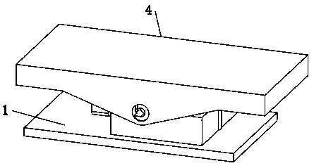
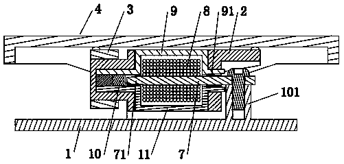
[0041] Such as Figure 1 to Figure 5 As shown, it is a micro power generation device, including a power generation structure, a base 1, a mounting sleeve 2 and a pressing seesaw structure 4; wherein

[0042] A mounting frame 101 is provided on the base 1, and shaft sleeves 102 are respectively provided on both sides of the mounting frame 101, and rotating shafts 21 are respectively provided on both sides of the mounting sleeve 2, and the two rotating shafts 21 are installed to rotate respectively. In the two shaft sleeves 102, the installation sleeve 2 is on the installation frame 101 and can swing up and down;

[0043] Described power generation structure comprises magnetic guide bar 7, electromagnetic coil 8, upper magnetic guide plate 9, permanent magnet 10 and lower magnetic guide plate 11; Described upper magnetic guide plate 9, lower magnetic guide plate 11 and permanent magnet 10 are all fixed on In the installation sleeve 2, the permanent magnet 10 is located between ...

Embodiment 2

[0052] Such as Figure 6 to Figure 10 As shown, it is a micro power generation device, including a power generation structure, a base 1, a mounting sleeve 2, a pressing seesaw structure 4 and an elastic sheet 6; wherein

[0053] An installation frame 101 is arranged on the base 1, and shaft sleeves 102 are respectively arranged on both sides of the installation frame 101, and a rotating shaft 21 is respectively arranged on both sides of the installation sleeve 2, and the two rotating shafts 21 rotate respectively. installed in the two shaft sleeves 102, so that the installation sleeve 2 can swing up and down on the installation frame 101;

[0054] Described power generation structure comprises magnetic guide bar 7, electromagnetic coil 8, upper magnetic guide plate 9, permanent magnet 10 and lower magnetic guide plate 11; Described upper magnetic guide plate 9, lower magnetic guide plate 11 and permanent magnet 10 are all fixed on In the installation sleeve 2, the permanent m...

Embodiment 3

[0062] Such as Figure 11 to Figure 14 As shown, it is a micro power generation device, including a power generation structure, a base 1, a mounting sleeve 2, a pressing structure 4 and an elastic sheet 6; wherein

[0063] The right part of the base 1 is provided with an installation frame 101, and the front and rear sides of the installation sleeve 2 are provided with an installation shaft 21. Can swing up and down within 101;

[0064] Described power generation structure comprises magnetic guide bar 7, electromagnetic coil 8, upper magnetic guide plate 9, permanent magnet 10 and lower magnetic guide plate 11; Described upper magnetic guide plate 9, lower magnetic guide plate 11 and permanent magnet 10 are all fixed on In the installation sleeve 2, the permanent magnet 10 is located between the left end of the upper magnetic guide plate 9 and the lower magnetic guide plate 11; the electromagnetic coil 8 is wound on the magnetic guide rod 7, and the electromagnetic coil 8 and...


PUM


Abstract

The invention relates to a miniaturized power generating apparatus. The miniaturized power generating apparatus is characterized by comprising a generating structure, a base, an installation sleeve and a pressing seesaw structure, wherein the installation sleeve is arranged on an installation frame and can swing up and down; the generating structure comprises a magnetic conductive rod, a solenoid coil, an upper magnetic conductive plate, a permanent magnet and a lower magnetic conductive plate; the upper magnetic conductive, the lower magnetic conductive plate and the permanent magnet are fixed in the installation sleeve, and the permanent magnet is disposed between the left end of the upper magnetic conductive plate and the left end of the lower magnetic conductive plate; the magnetic conductive rod is fixed on the installation frame, the left end of the magnetic conductive rod is close to the permanent magnet and is disposed between the left end of the upper magnetic conductive plate and the left end of the lower magnetic conductive plate, the right end of the magnetic conductive rod is disposed between the right end of the upper magnetic conductive plate and the right end of the lower magnetic conductive plate, and the upper magnetic conductive plate and the lower magnetic conductive plate can swing up and down relative to the solenoid valve and the magnetic conductive rod; and the pressing seesaw structure is rotationally arranged on the base, and the pressing seesaw structure drives the left end and the right end of the installation sleeve to swing up and down. The miniaturized power generating apparatus has the advantages of high work reliability, large generating capacity and small volume, thereby satisfying a round-the-clock long application demand for users, is economical and environmentally friendly, and is wide in adaptability.

Description

technical field [0001] The invention relates to a micro power generation device. Background technique [0002] Electronic products are widely used in daily life, and low-power electronic products generally use batteries as power sources for their work, such as electrical switches, electronic doorbells, and remote controls. The use of batteries as a power source has limitations. Its service life is short, and the batteries need to be replaced regularly. The user's use costs are high. Also, because the batteries are prone to rust and leakage, the reliability of electronic products will be greatly reduced, and they cannot meet all-weather long-term requirements. The need to provide energy brings inconvenience to users; manufacturing batteries not only consumes resources, but also a large number of used batteries are discarded, polluting the environment. At present, there is a micro power generation product, but its power generation is small and cannot completely replace the ba...

Claims


Application Information

Patent Timeline
Patent Type & Authority Patents(China)
IPC IPC(8): H02K35/02
CPCH02K35/02
Inventor 吴建忠黄智
Owner FOSHAN SHUNDE ADVANTE ELECTRON LTD
Why Eureka
Try Eureka