Moving and static stabilizer between spine plates

A technology of stabilizer and spine plate, which is applied in medical science, prostheses, spinal implants, etc., can solve problems such as weakened distraction, decreased intervertebral space and intervertebral foramen height, and difficulty in ensuring long-term effects. Achieve the effect of ingenious design and simple structure

Pending Publication Date: 2018-12-18
李照文
View PDF1 Cites 0 Cited by
  • Summary
  • Abstract
  • Description
  • Claims
  • Application Information

AI Technical Summary

Problems solved by technology

At present, some new patented technologies have appeared, such as the interspinous dynamic stabilizer with application number 201610667104.7, which can not only perform extension and flexion in the sagittal position of the spine, but also perform lateral bending and rotation. The elastic part is arc-shaped. After long-term use, it will be deformed due to elastic attenuation, so that it cannot maintain a lasting stretching force at the root of the spinous process. As it is used for a long time, it will appear at the root of the spinous process. The height of the distraction decreases, which leads to a corresponding decrease in the height of the intervertebral space and the intervertebral foramen, which weakens the original distraction effect and makes it difficult to ensure a good long-term effect
[0004] In addition, the movement of the human spine is not limited to extension and flexion, lateral bending and rotation, but also the front-back translation and left-right lateral movement between the vertebrae. However, the existing technology cannot solve this problem well, so it is necessary to develop a A kind of stabilizer to solve the above-mentioned problems that existing stabilizer exists

Method used


Image

  • Moving and static stabilizer between spine plates
  • Moving and static stabilizer between spine plates
  • Moving and static stabilizer between spine plates

Examples


Embodiment Construction

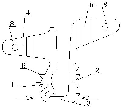
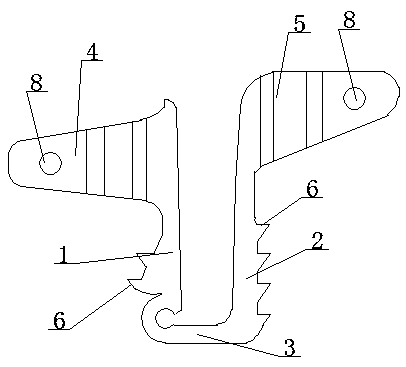
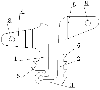
[0035] The dynamic and static stabilizer between the ratchet plates is an integrated structure, which is composed of a first connecting part 1, a second connecting part 2, an engaging part 3, a first fixing part 4 and a second fixing part 5; both sides of the connecting part 3 The first connecting part 1 and the second connecting part 2 are respectively provided; the upper end outer surface of the first connecting part 1 is respectively provided with the first fixing part 4 symmetrically; the upper end outer surface of the second connecting part 2 is respectively provided with the second Two fixed parts 5 (see the attached Figure 1-14 ).

[0036] The middle part of the joint part 3 is provided with or without a clearance groove 9 (see the appended Figure 5 or 6). When the gap groove 9 is provided on the connecting part 3, when the vertebral segments move sideways, the deformation space of the connecting part 3 is larger, which is more suitable for the needs of the patient....


PUM


Abstract

The invention relates to a moving and static stabilizer between spine plates, and belongs to the technical field of imbedded objects in human body of medical devices. The moving and static stabilizeris of an integrated structure and is formed by a first connection part, a second connection part, an engagement part, first fixed parts and second fixed parts. The first connection part and the secondconnection part are respectively arranged on two sides of the engagement part. The first fixed parts are symmetrically arranged on outer side face of the upper end of the first connection part. The second fixed parts are symmetrically arranged on the outer side face of the upper end of the second connection parts. The engagement part is of a straight plate-shaped structure. According to the invention, elastic supporting-away between spines and front and back bending of the spine can be achieved; front and back translation and left and right lateral movement between vertebra joints can be achieved; in addition, the stabilizer is not forced to be embedded to be close to the spinal dura mater, the operation time is short, the operation safety is high and the stabilizer can be used for caseswith quite small spine interval; and long-term use demands of patients are met.

Description

technical field [0001] The invention relates to a dynamic and static stabilizer between spine plates, which belongs to the technical field of implants in the human body of medical instruments. Background technique [0002] At present, spinal fusion technology has achieved good results in the treatment of neck and back pain and instability of the cervical and lumbar spine, with a fusion rate of over 90%. However, after spinal fusion, there will be loss of spinal motion at the fused segment and accelerated degeneration of adjacent segments. In view of this, many scholars have devoted themselves to the study of spinal non-fusion technology in recent years, and there are more and more corresponding products. It can stabilize the diseased segment while retaining the mobility of the diseased segment, and is not prone to the characteristics of accelerated degeneration of adjacent segments. The implantation of the interspinous process or interspinous plate dynamic stabilizer in the...

Claims


Application Information

Patent Timeline
Patent Type & Authority Applications(China)
IPC IPC(8): A61F2/44
CPCA61F2/4455A61F2220/0025
Inventor 李照文李绪贵谢维
Owner 李照文
Why Eureka
Try Eureka