
Method and device for transmitting and receiving client signal in optical transport network

一种光传送网、客户信号的技术,应用在光传送网领域,能够解决无法达到光传送网带宽资源最优化配置、无法提供线路接口等问题

Active Publication Date: 2017-01-04
HUAWEI TECH CO LTD
View PDF4 Cites 7 Cited by
  • Summary
  • Abstract
  • Description
  • Claims
  • Application Information

AI Technical Summary

Problems solved by technology

[0006] However, the current line interface of the electrical layer OTN is a fixed rate level, and it is impossible to provide a line interface with a suitable rate according to the actual traffic volume of customer services, so that the optimal allocation of bandwidth resources of the optical transport network cannot be achieved.

Method used


Image

  • Method and device for transmitting and receiving client signal in optical transport network
  • Method and device for transmitting and receiving client signal in optical transport network
  • Method and device for transmitting and receiving client signal in optical transport network

Examples


Embodiment Construction

[0030] In order to make the object, technical solution and advantages of the present invention clearer, the implementation manner of the present invention will be further described in detail below in conjunction with the accompanying drawings.

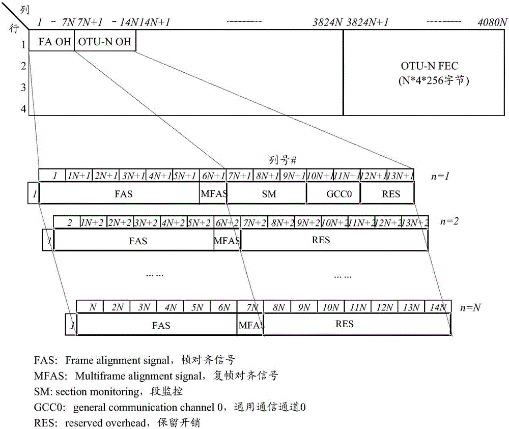
[0031] In the embodiment of the present invention, a variable-rate container structure is constructed on the OTN electrical layer, which is called OTU-N (Opticalchannel Transport Unit-N, Optical Channel Transport Unit-N). The value N is a configurable positive integer. The OTU-N The rate of N is configurable at a granularity of a preset base rate level, for example, the rate of the OTU-N is N times the base rate level. The rate of the OTU-N can be flexibly configured according to the traffic size of the client signal, which can be detected by the OTN equipment or configured by the management plane.

[0032] The value N is flexibly configured according to transmission requirements. Preferably, the value N is determined based on the traf...


PUM


Abstract

The embodiment of the invention provides a method and a device for transmitting and receiving a client signal in an optical transport network, and belongs to the field of the optical transport network. The transmitting method comprises the following steps: mapping the received client signal to a container OTU-N with a variable rate, wherein the rate of the OUT-N is N times that of the preset reference rate grade, and N is a configurable positive integer according to requirements; dividing the container OTU-N with the variable rate into N photon channel transmission units OTUsub according to columns, wherein the rate of each OTUsub is equal to the reference rate grade; modulating the N photon channel transmission units OTUsub to one-channel or multi-channel optical carriers; transmitting the one-channel or multi-channel optical carriers to the same optical fiber to perform transmission. According to the embodiment of the invention, the client signal is mapped to the container OTU-N with the variable rate and the OTU-N is transmitted by the same optical fiber, so that the method and the device can be adaptive to the change of spectral bandwidth of an optical layer, and optimized configuration of the bandwidth resources of the optical transport network is realized.

Description

technical field [0001] The invention relates to the field of optical transport network, in particular to a method and device for transmitting and receiving client signals in the optical transport network. Background technique [0002] OTN (Optical transport network, optical transport network), as the core technology of the next-generation transport network, includes the technical specifications of the electrical layer and the optical layer, and has rich OAM (Operation Administration and Maintenance, operation, management and maintenance), powerful TCM (Tandem Connection Monitoring (tandem connection monitoring) capability and out-of-band FEC (Forward Error Correction, forward error correction) capability can realize flexible scheduling and management of large-capacity services. [0003] At the electrical processing layer, OTN technology defines a standard encapsulation structure, maps various customer services, and can manage and monitor customer signals. OTN frame structur...

Claims


Application Information

Patent Timeline
Patent Type & Authority Applications(China)
IPC IPC(8): H04J3/16H04J14/02
CPCH04J3/1652H04J14/0298H04B10/25H04J3/1694H04B10/27H04B10/516
Inventor 苏伟吴秋游董立民
Owner HUAWEI TECH CO LTD
Learn More